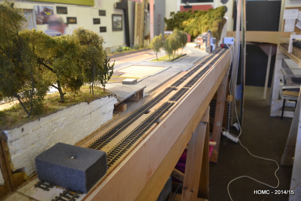
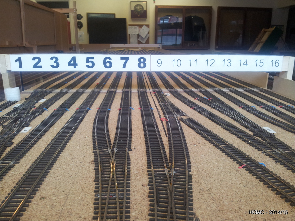
We’ve carried on working hard since last November and have pretty much completed all the baseboard work now. It’s not shown in any detail, but we cut the old staging yard off the back of the main baseboards, leaving just two tracks, which are for testing and programming – one will be DC. A 1ft strip was also removed from the left hand (tunnel) end to give a total modelled board length of 20ft to match the staging yard.
The cutting was done with a rotary saw and finished with a hand saw. The edges were then faced with fresh plywood, suitable braced, glued and screwed. To finish this part of the reconstruction the remnant rear main boards (now about 4ft x 1ft6in) were permanently attached to the front main boards (the original 4ft x 2ft6in) using PVA glue and screws through the bracing points. This means that we have four boards 4ft square and two narrow end boards – one 4ft x 1ft6in and one 4ft x 2ft6in – slightly awkward but – hey!
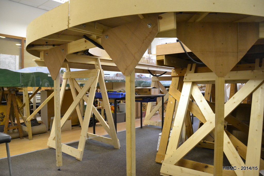
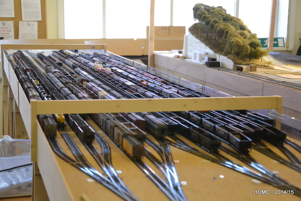
The photos show the new centre well that this configuration gives us – big enough for even the larger of us (I won’t say who that is!) to move comfortably along, although we can’t easily pass except in the ends.
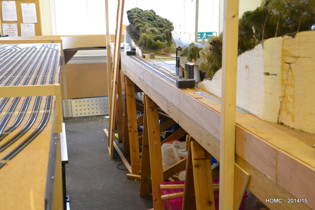
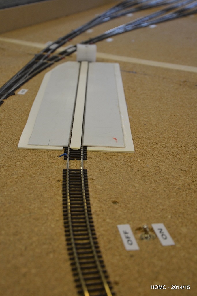
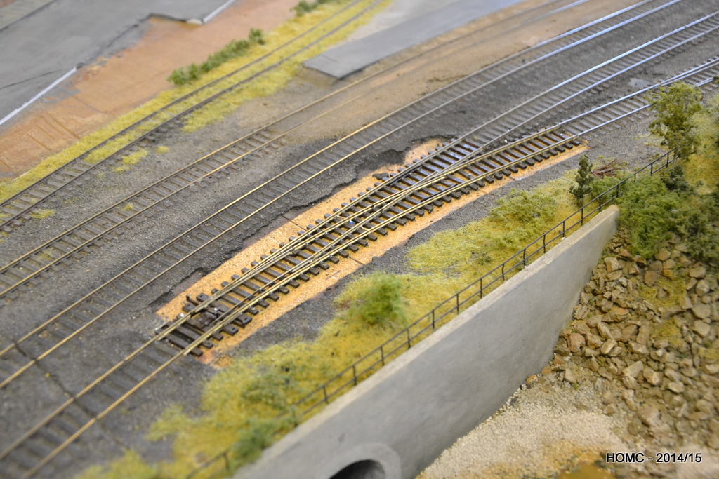
New legs were constructed for the end curves. Also shown above and below is a (re-) railing track which is switched to avoid shorts. Connecting the boards up in the final configuration meant that we could finally lay the connecting track at both ends – shown below.
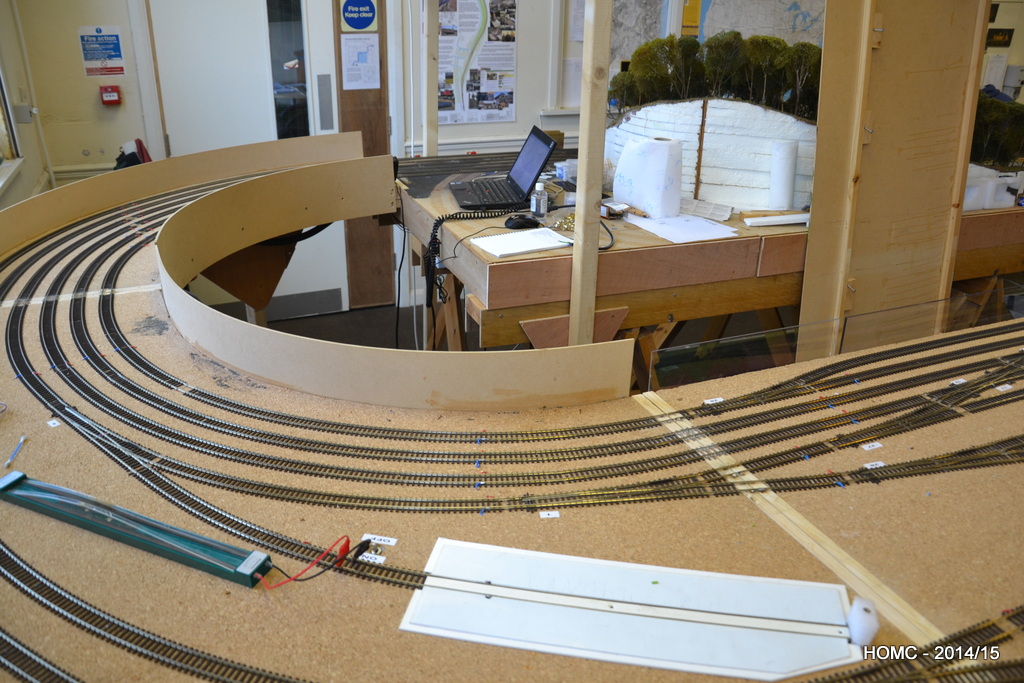
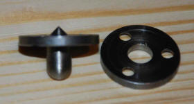
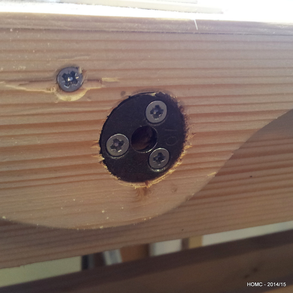
A brief diversion here into the techniques used to ensure that where the track crosses a baseboard join, the stock doesn’t derail. Portable baseboards are the norm in the UK and so this is a major problem. Critical to ensuring that track stays aligned is ensuring that baseboards align in the same position each time they are reattached. The best way to do this is to use board alignment dowels. The best ones have a point in the back of one side that lets you align the two sides for drilling. The second and third photos show these in our board (after the curvy edge system had failed to align the boards well enough!).


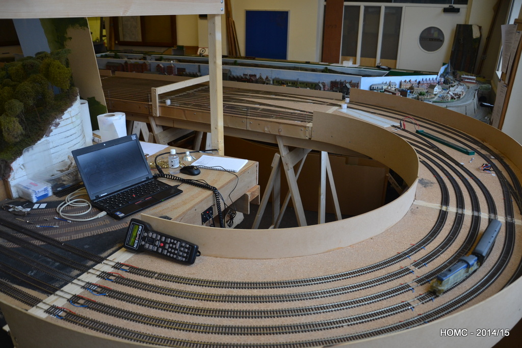
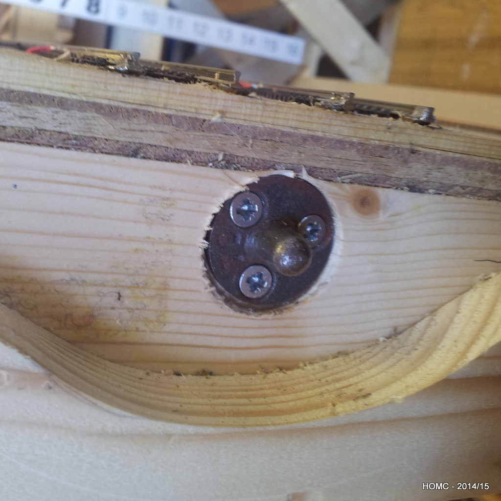

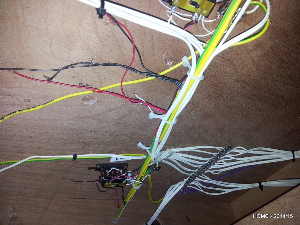
The wiring on the front had been installed many years ago, and so the switch control wiring was disconnected and then rewired to MERG DCC boards to give the same switch control system as in the staging yard. Note that the DCC switch control boards are always attached to a vertical surface to make maintenance easier. One switch on the front (on a curve) was replaces with a commercial Peco switch – which has proved better, but not perfect.
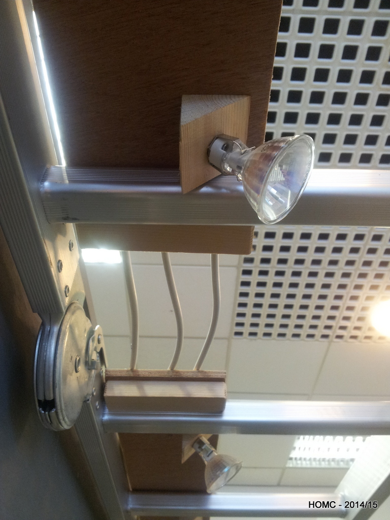
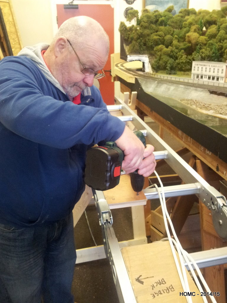
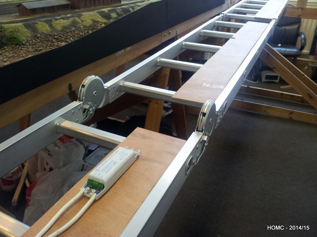
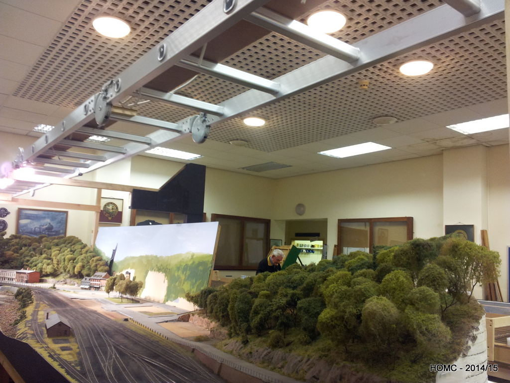
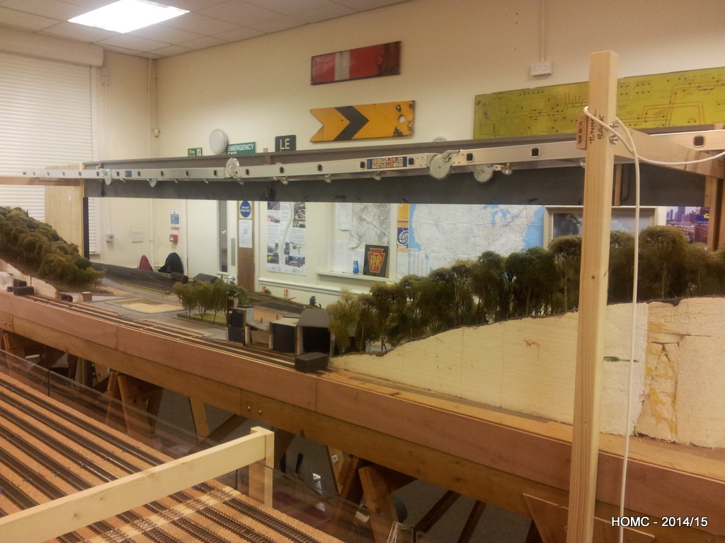
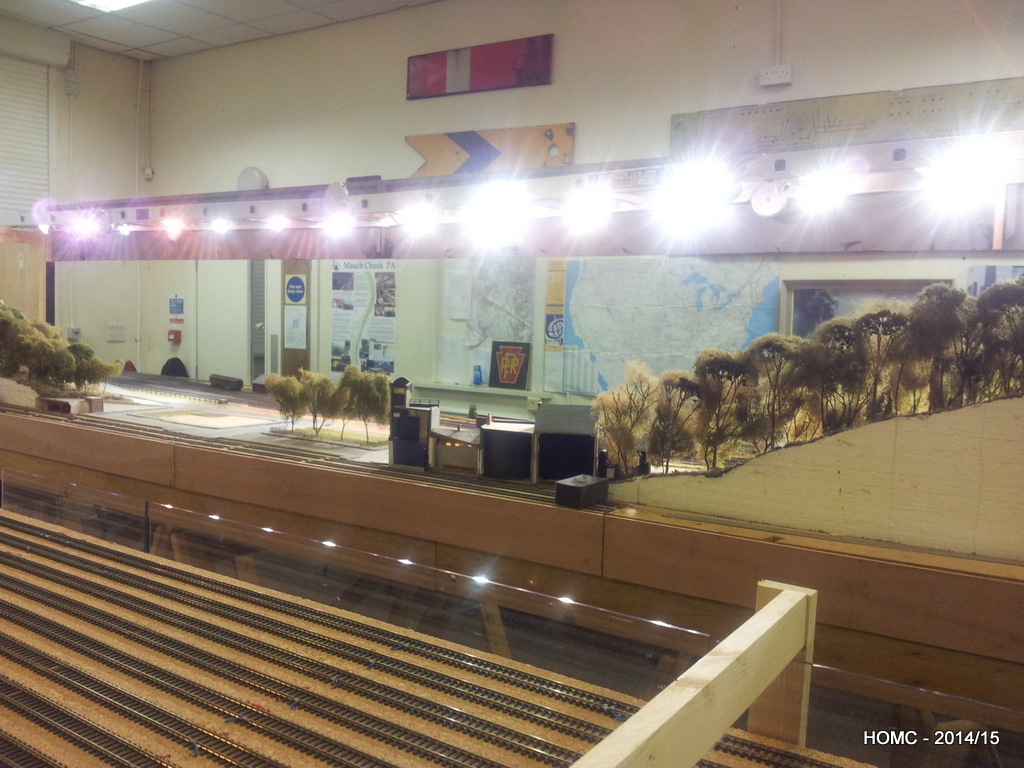
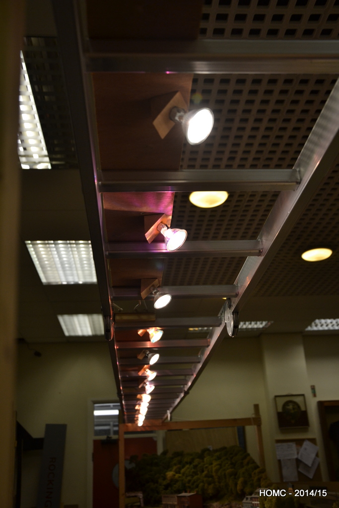
Everything working on the boards, we then moved on to the lighting and the gantry. After seeing a layout at the Mickleover (Derby) club using an aluminium folding ladder to support the lighting, we managed to purchase a 20ft ladder that would work for us. Although it was not completely level when supported at only the ends, it was rigid and so the slight central dip could be accommodated when mounting the fascia boards.
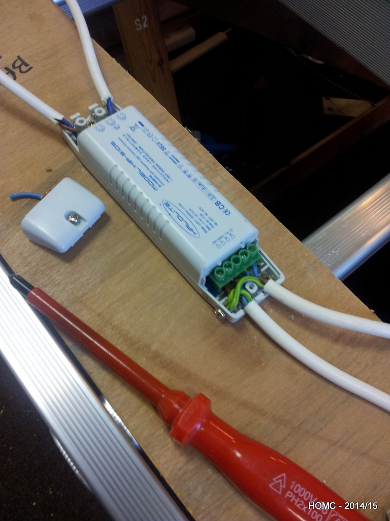
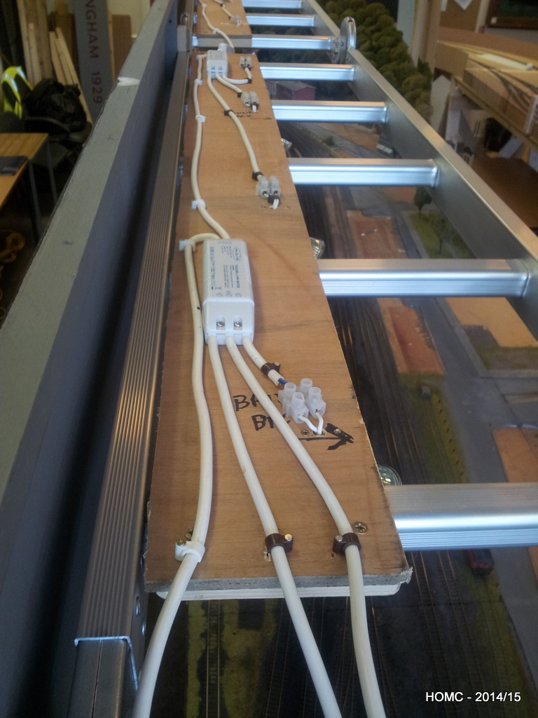
Lights are DC (12v) halogen, wide angle floods of 20, 35 and 50 watts. We attached these to the bottom of strips of plywood at 45 degree angles with basic lampholder bases. Along the top of each board were the transformers and the wiring. The plywood simply rests on top of the ladders and the fascia hangs off the front. A simple H frame at each end supports the ladder.
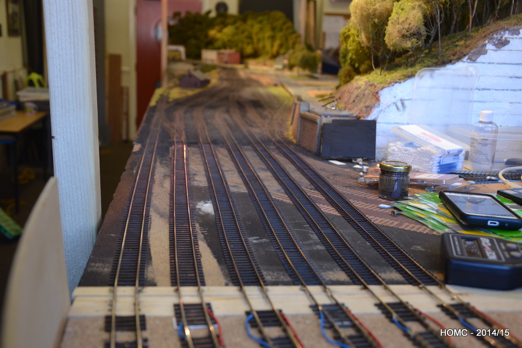
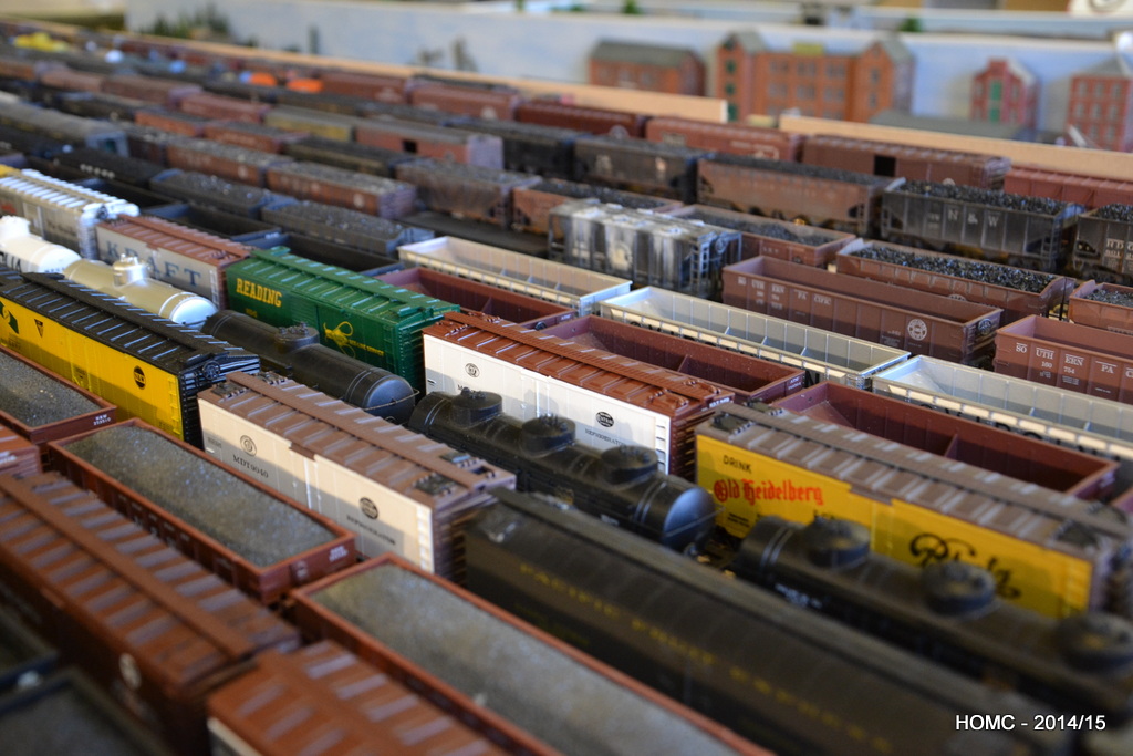
All this work completed, we decided to put our stock out on the staging yard and were quite shocked by how much we had – especially as most of our locos can’t pull such long trains. Still quite a lot of weathering, re-wheeling and Kadee-ing to be done though!
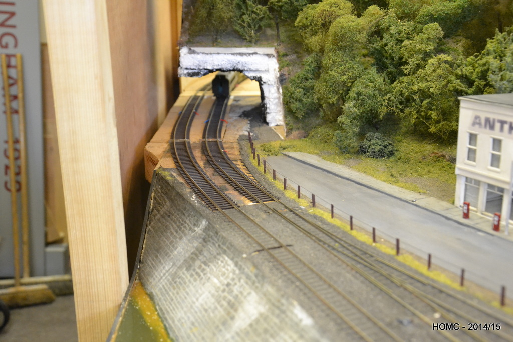
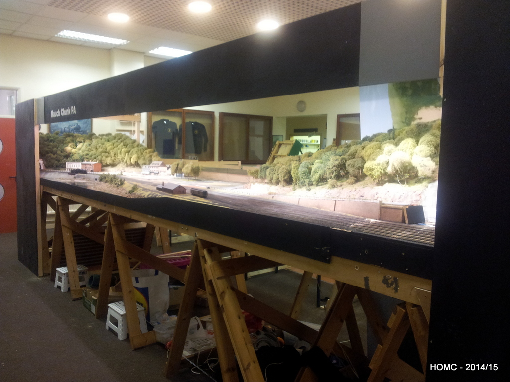
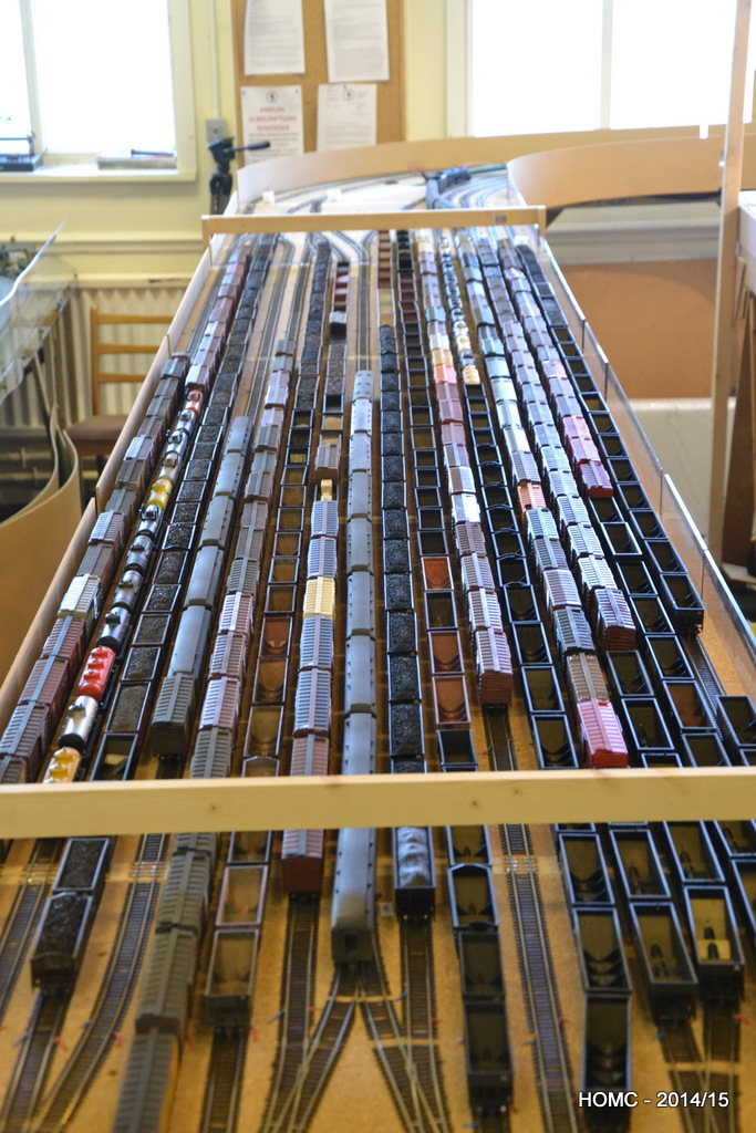
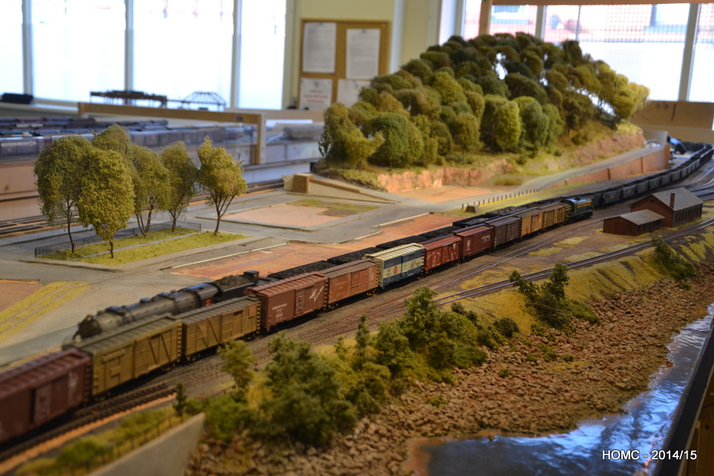
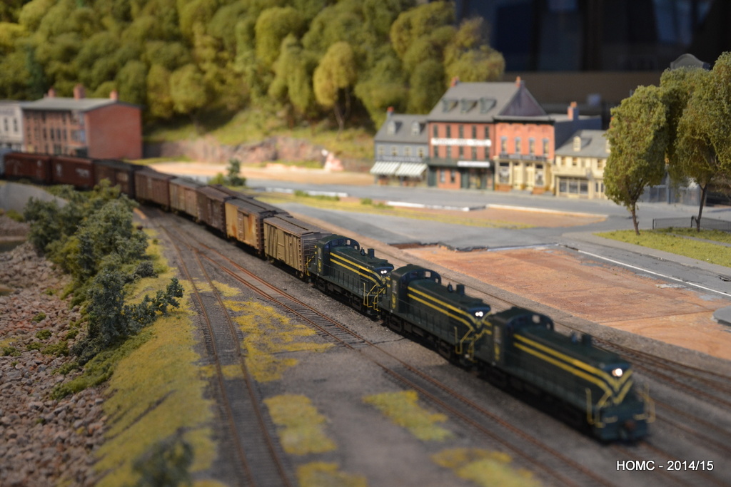
Finally a shot showing a consist of new (as yet undetailed) Athearn RS3s and then one with a N&W articulated interloper with a long empty coal train (note that the buildings have been removed for safe keeping). We are now moving on to add more hillside and roadway at the RH end, and then will work along adding detail to the scenery.