We’ve been doing more etches and soldering to make the signal gantry that stands against the back wall, controlling use of the locomotive servicing track that runs against that wall all the way through to the engine house, refueling facility and turntable.
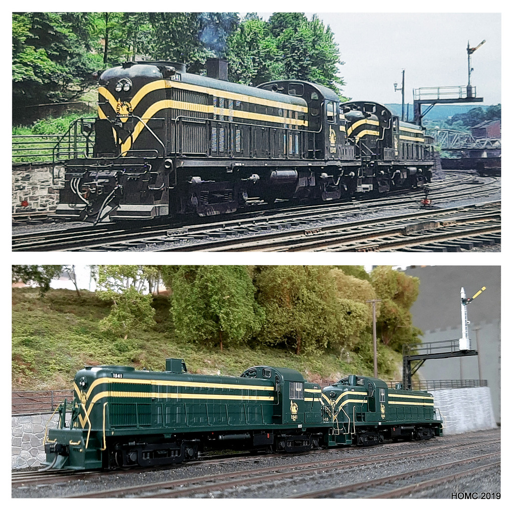
Photos of this gantry were not clear about all the features so similar gantries were identified in Joel Rosenbaum and Tom Gallo’s pdf book: Jersey Central Lines Official Photography. Steve drew the stanchion artwork and PPD then etched these for us on 0.7mm brass. Richard then used these as the basis for the gantry scratchbuilding most of the other components. Finally the arm was actuated with a servo controlled by Tam Valley Depot’s dual 3-way Servo DCC accessory decoder. This is a new approach for us and means that we can control the signal from software (Big Bear) as well as push buttons. The build is shown here as well as the result
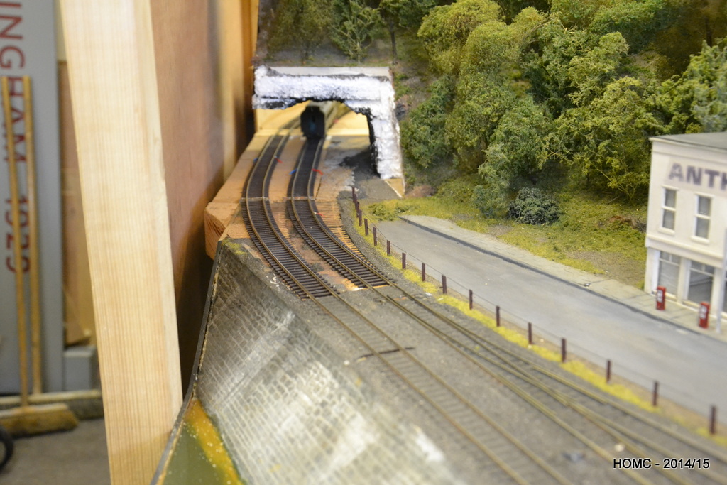
This is our gantry compared with the prototype shot! Prototype photo by kind permission of Morning Sun Books [taken by Charles Houser Sr, The Houser Collection from page 82 of Jersey Central Lines in Color Volume 2 by William J. Brennan].
As well as this masterpiece, the hollow framework utility cable posts that can be seen in some prototype photos were drawn up by Steve, etched and then built by Richard using bullhead rail for the sides. Steve then planted them on the layout and modified a few other posts.
The trolleys get a lot of wear in transporting Mauch Chunk to exhibitions but also in supporting the other Barrowmore layout, Johnstown Road, when Mostyn is erected. We decided to strengthen the trolleys with easily removed ‘lids’ which Gavin built. This has made the trolley boxes much more rigid
We have started working again on Mauch Chunk since getting back from a succesful exhibition in Glasgow. We had two problems there that impacted on operations, although hopefully the public didn’t see anything substantially wrong.
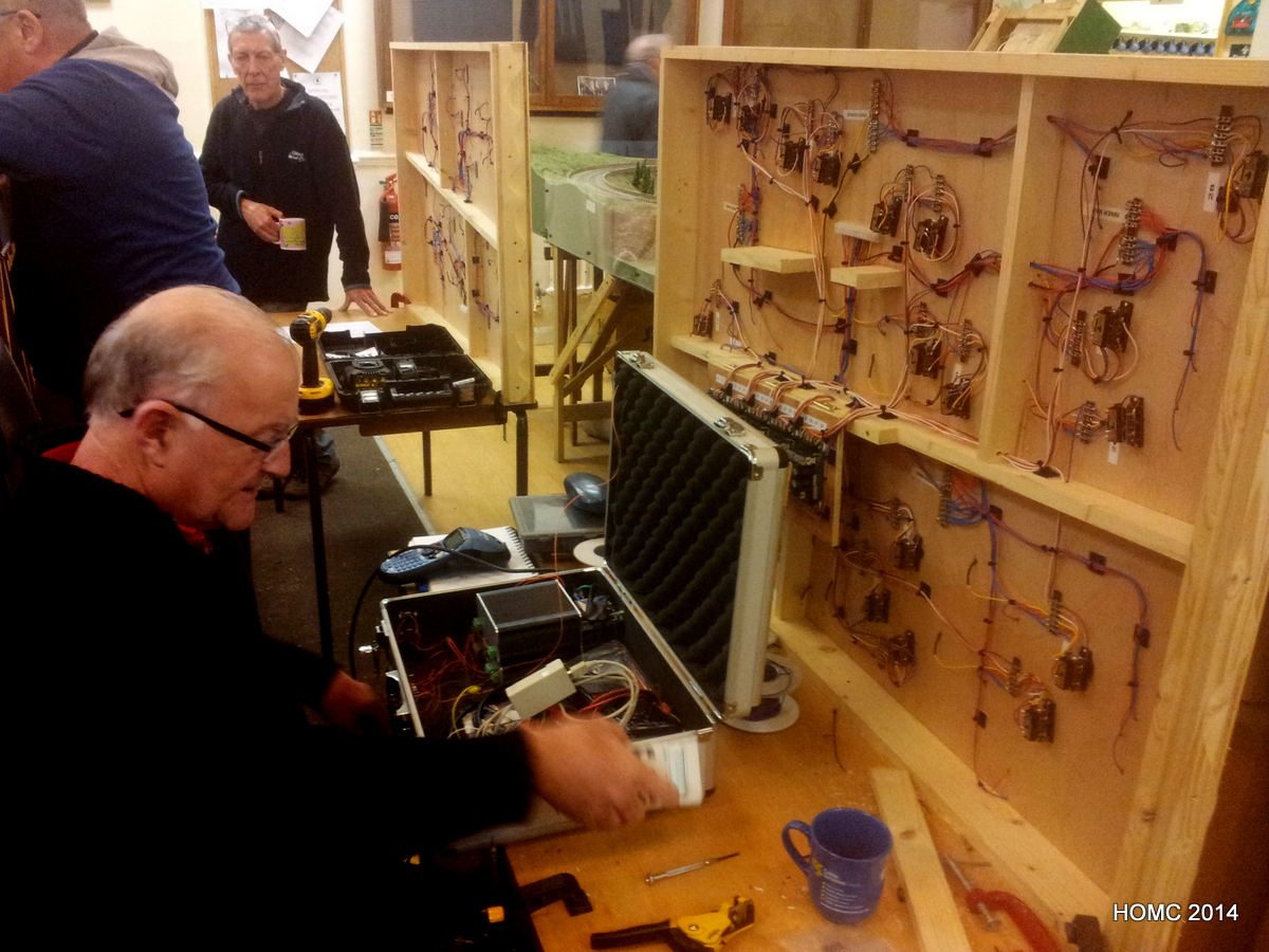
Firstly we had overheating of the Lenz LZV100 command station. This was partly because I didn’t take the lid completely off the really useful box we’re using for the control panel. However, overheating did occur again later even when the box was completely open. Clearly passive air cooling isn’t enough when we are operating so intensively for 7 – 8h periods.
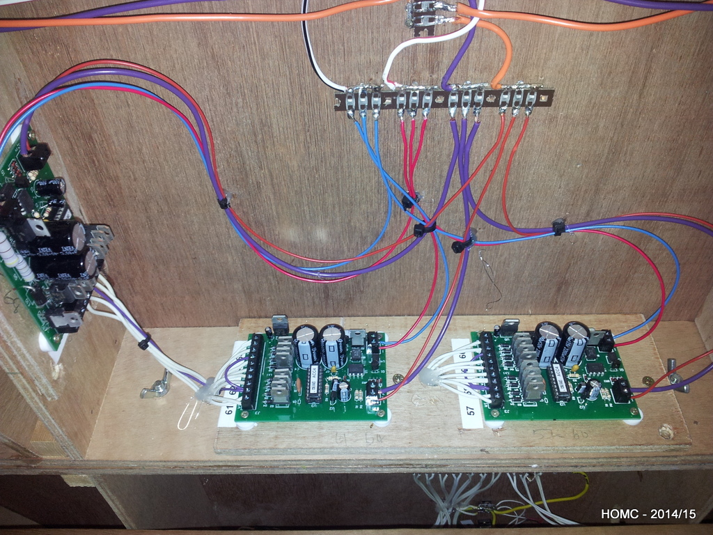
To remedy this, Gavin has put a fan in one end of the box, holes in the other and reorganised the interior to allow a good airflow. The Lenz LZV100 is now also mounted on a hollow support to allow airflow beneath as well. It should work nicely and will allow us to leave the lid on next time!
To put the icing on the cake he (and Dave Faulkner) have also wired the block protector boards to LEDs that display when a short is occuring – this will make it much quicker to detect problems.
Secondly, we had problems with the Peco point motors (in the staging yard) misbehaving. This is likely to be due to poory alignment/positioning which has occured as a result of heavy use and the way that they operate – with a thud in each direction.
We decided to try a servo design which has a more genteel motion. As there was not enough vertical space for Tortoise motors, have gone for MP-1 point motors from MTB Model (click here) in Prague. These are supplied by DCC Train Automation in the UK (click here). To control these with DCC we also purchased Digikeijs DR4018 accessory decoders, also from DCC Train Automation (click here) which each control eight motors.
We had to include some cross-baseboard links for control to avoid wasting the channels on the accessory decoders. Although it is a pain to replace and rewire all the motors in the yard, provisionally it looks as though it will be a good investment. We will report here on our experiences.
Mostyn is to be exhibited at Alexandra Palace (London) towards the end of March, so most work stopped on Mauch Chunk during the period leading up to this.
Some work has been going on: I have rewired the board connectors on the four ‘old’ large scenic boards using 12-way Mat-N-Lok connectors as with the rest of the layout. This brings all the wiring to the same standard.
Passenger and parcel stock has been re-Kadeed to allow for closer and more reliable level coupling. We have also started to add corridor connectors. Seven more cabooses are beeing worked on to have their eighth window removed and will then be repainted and decalled.
Finally the Mauch Chunk boards, on their trolleys, were stacked underneath the O-Gauge ‘Johnstown Road’ layout while Mostyn was put up.
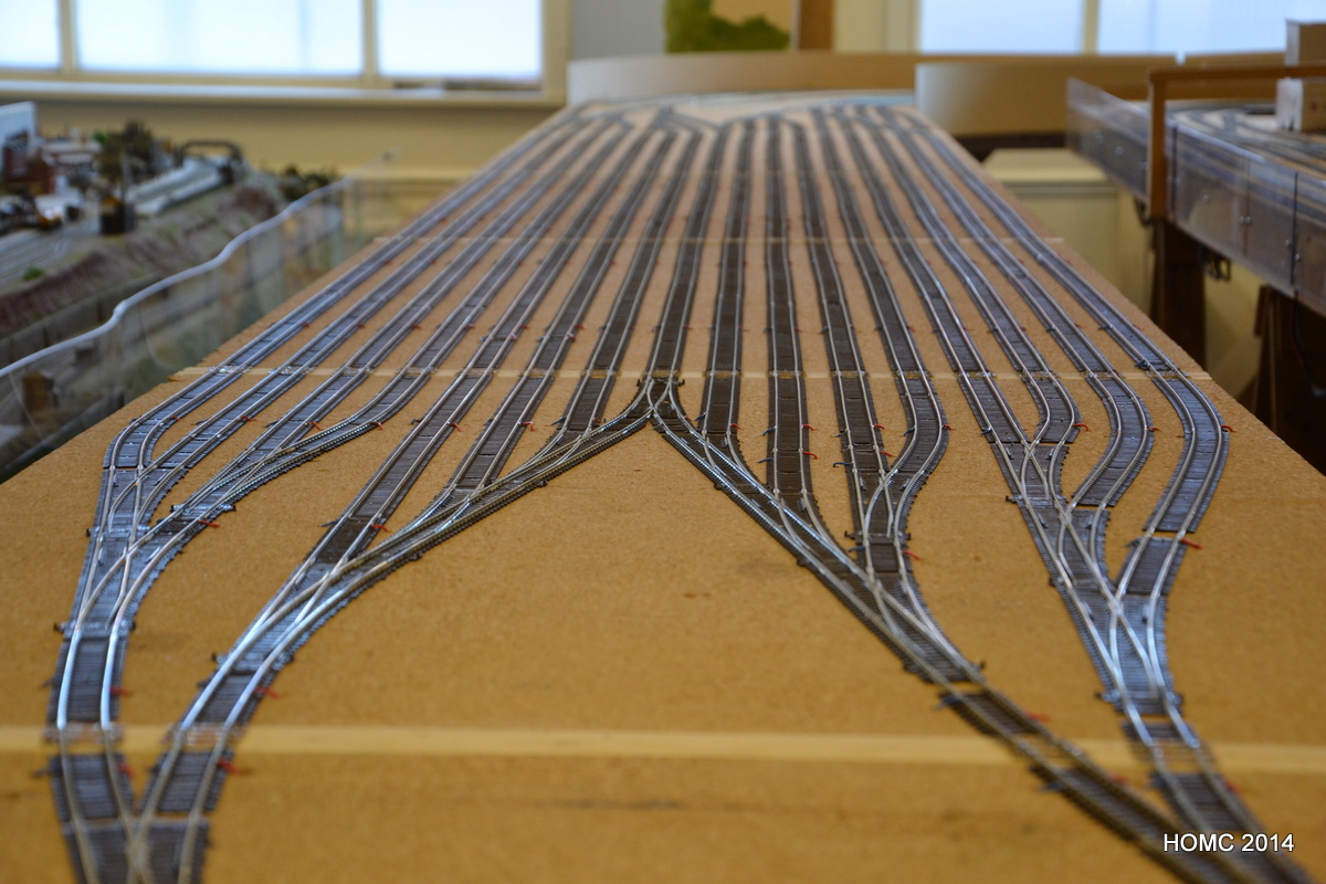
To support the new turnout and trackwork, Steve has added Tortoise point motors and new MERG boards – build by Derek jones of Merseyside MRS – to control them. As well as this, all the ‘droppers’ had to be connected and rather than use the old track buses, new, taught ones were added to match the style of the staging yard as well as the other Barrowmore Layouts. Only the inter-board connectors were not changed at this time.
Although some wiring is continuing, most of it was done in the ten days to 5th April by Richard and Steve, with significant input by Dave (& even a couple of hours by the hard-working Gareth!).
All the droppers are connected onto track buses – one ‘westbound’ and one ‘eastbound’.
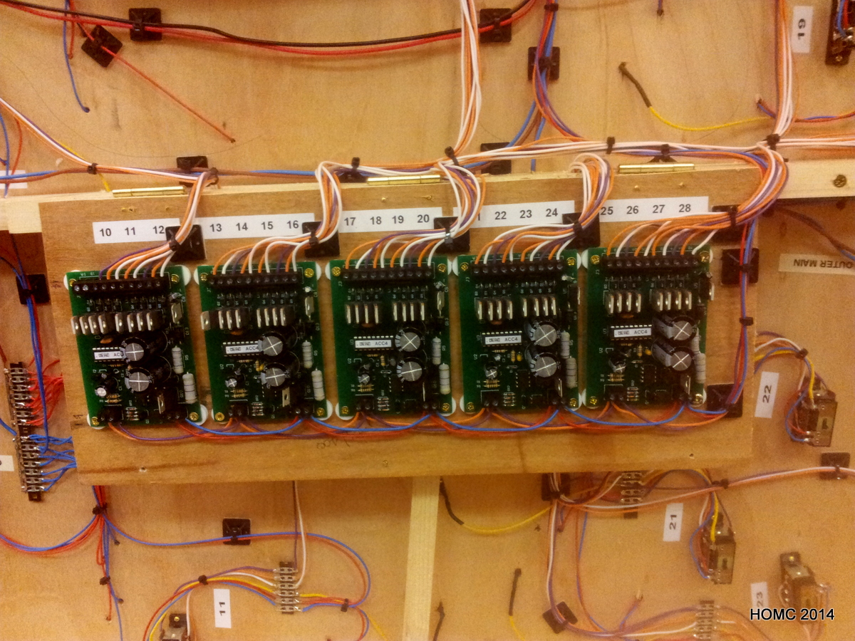
The approach for the turnouts has been to use Peco turnout motors on the Peco turnouts. These are connected through to ‘frog juicers’ built to a published circuit by a member of Merseyside MRS. These are supposedly more reliable than the physical switches that sit on the motors which are currently still in use on the scenic section. Frog juicers are necessary because electrofrog turnouts are used. The turnout motors are connected in fours to MERG boards, made up by Derek Jones of MMRS. This type of MERG board has a DCC accessory feed (two wires) and a trickle charge feed (two wires) to charge the capacitors.
Finally, a Lenz expressnet link is fed through and taken to DIN sockets on the sides of the board wherever one is needed. The total 12 wires for each (most) boards are connected from board to board using a wiring loom fed into Mate-n-Lok 12 pin connectors which look like a cheap and reliable connection option.
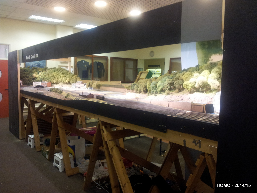
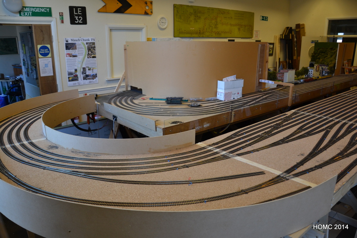
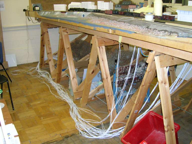
We’ve carried on working hard since last November and have pretty much completed all the baseboard work now. It’s not shown in any detail, but we cut the old staging yard off the back of the main baseboards, leaving just two tracks, which are for testing and programming – one will be DC. A 1ft strip was also removed from the left hand (tunnel) end to give a total modelled board length of 20ft to match the staging yard.
The cutting was done with a rotary saw and finished with a hand saw. The edges were then faced with fresh plywood, suitable braced, glued and screwed. To finish this part of the reconstruction the remnant rear main boards (now about 4ft x 1ft6in) were permanently attached to the front main boards (the original 4ft x 2ft6in) using PVA glue and screws through the bracing points. This means that we have four boards 4ft square and two narrow end boards – one 4ft x 1ft6in and one 4ft x 2ft6in – slightly awkward but – hey!
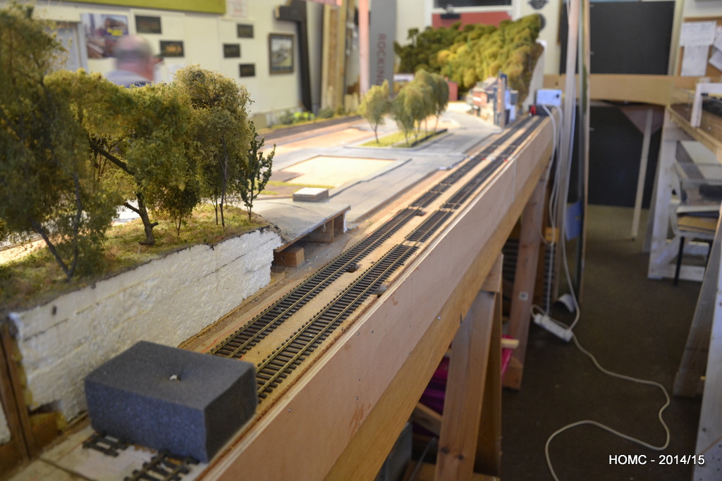
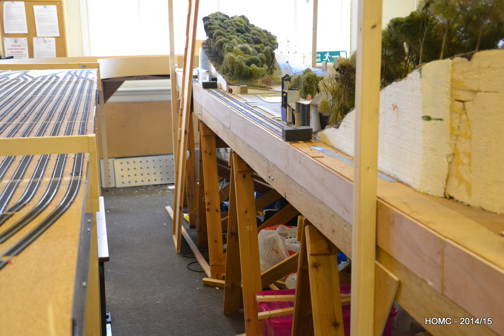
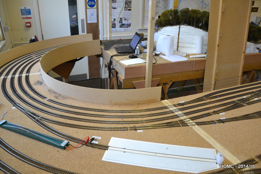
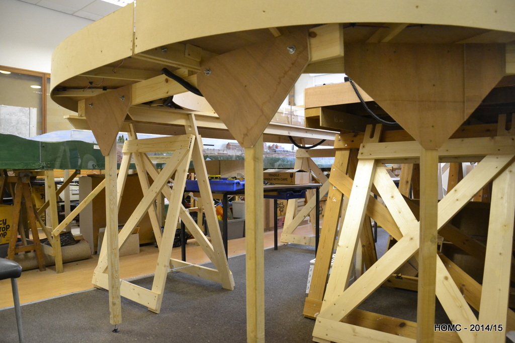
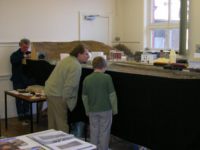
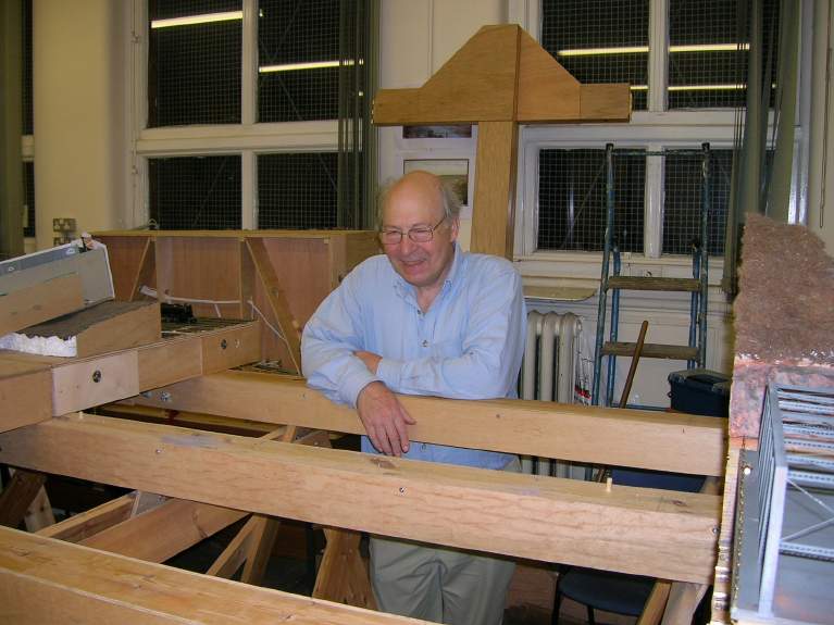
The photos show the new centre well that this configuration gives us – big enough for even the larger of us (I won’t say who that is!) to move comfortably along, although we can’t easily pass except in the ends.
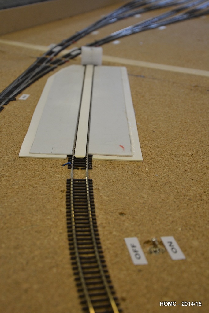
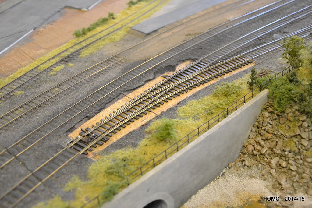
New legs were constructed for the end curves. Also shown above and below is a (re-) railing track which is switched to avoid shorts. Connecting the boards up in the final configuration meant that we could finally lay the connecting track at both ends – shown below.
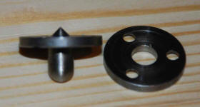
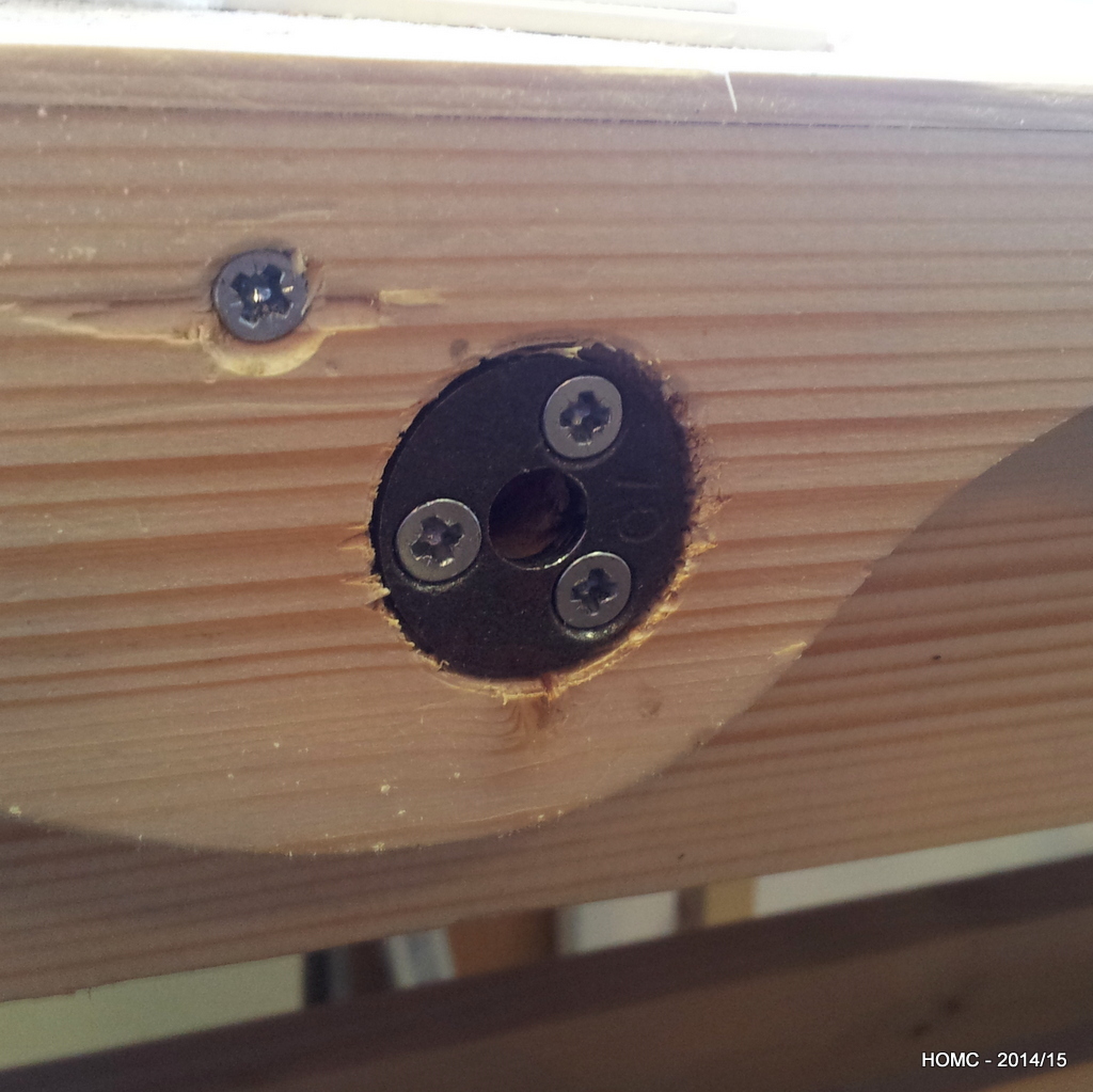
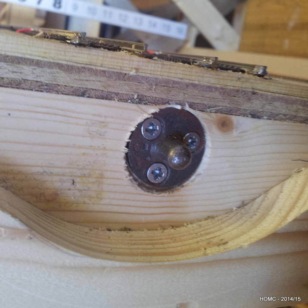
A brief diversion here into the techniques used to ensure that where the track crosses a baseboard join, the stock doesn’t derail. Portable baseboards are the norm in the UK and so this is a major problem. Critical to ensuring that track stays aligned is ensuring that baseboards align in the same position each time they are reattached. The best way to do this is to use board alignment dowels. The best ones have a point in the back of one side that lets you align the two sides for drilling. The second and third photos show these in our board (after the curvy edge system had failed to align the boards well enough!).
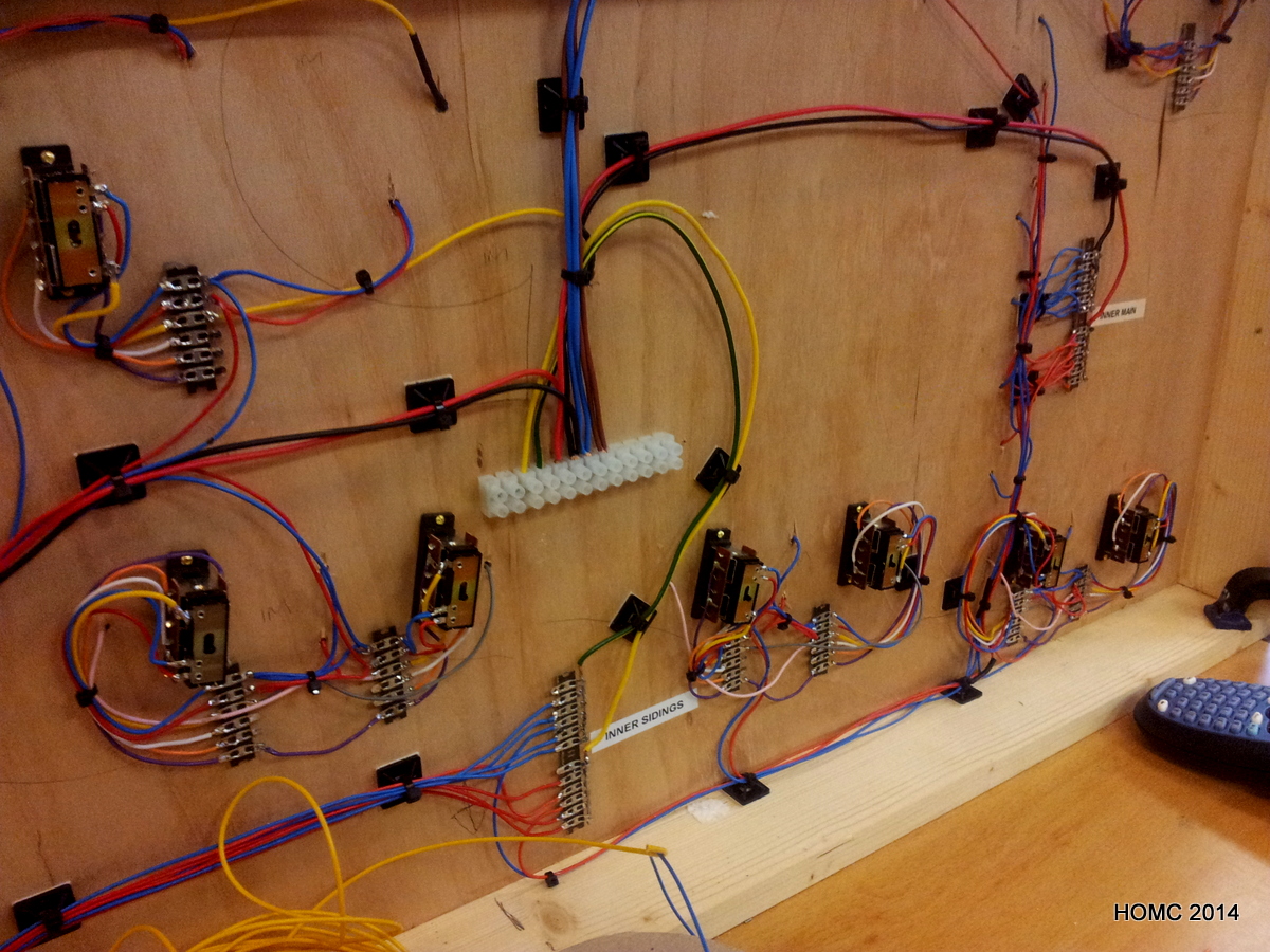
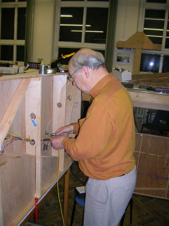
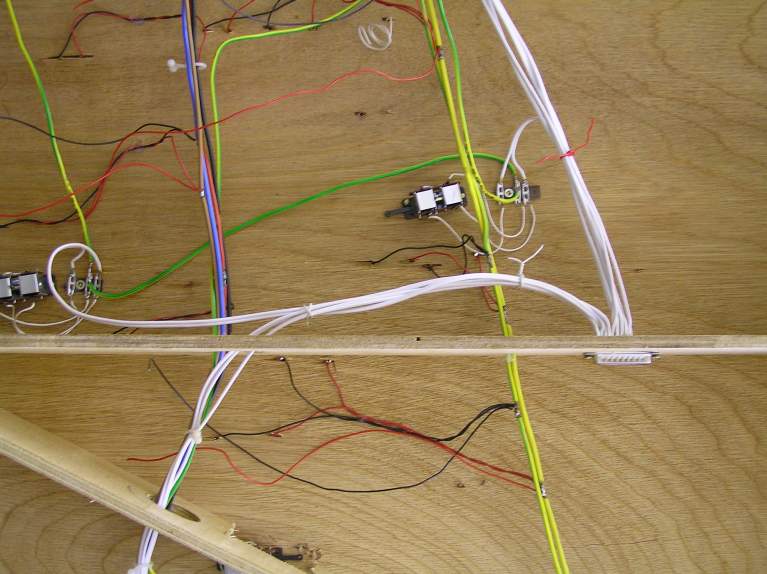
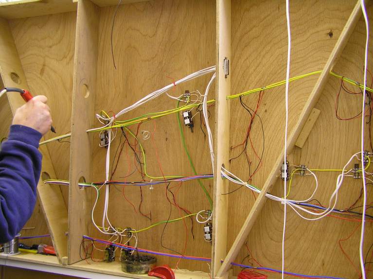
The wiring on the front had been installed many years ago, and so the switch control wiring was disconnected and then rewired to MERG DCC boards to give the same switch control system as in the staging yard. Note that the DCC switch control boards are always attached to a vertical surface to make maintenance easier. One switch on the front (on a curve) was replaces with a commercial Peco switch – which has proved better, but not perfect.
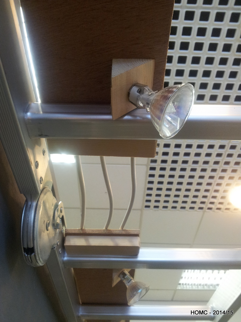
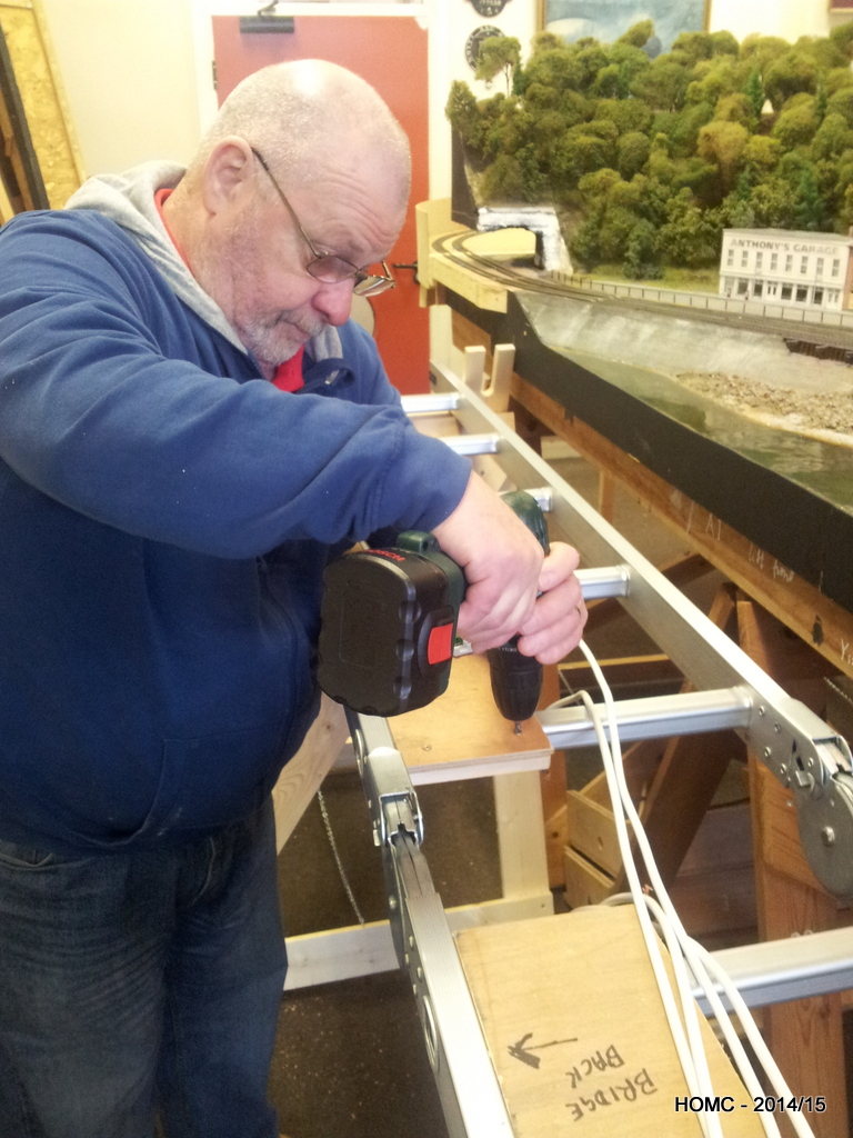
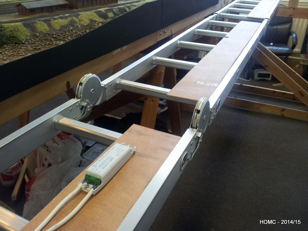
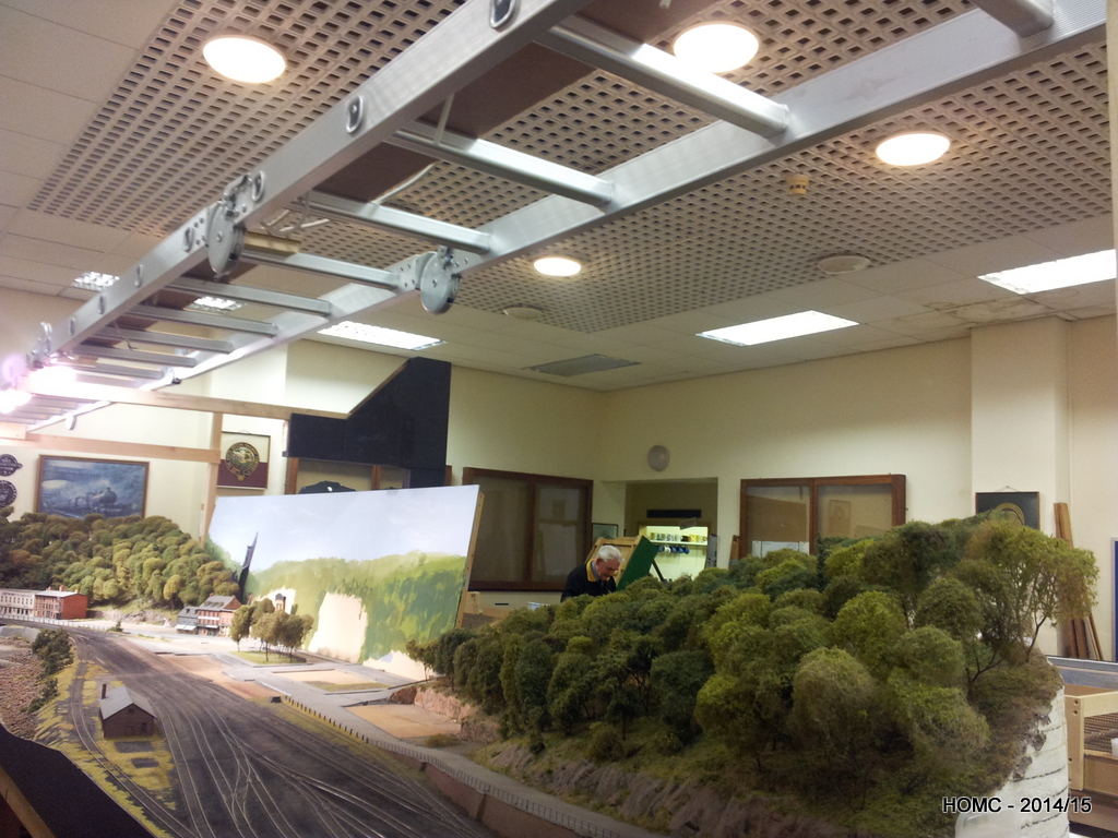
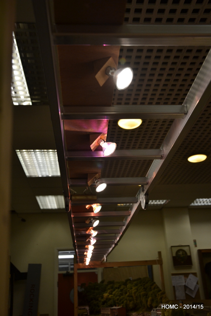
Everything working on the boards, we then moved on to the lighting and the gantry. After seeing a layout at the Mickleover (Derby) club using an aluminium folding ladder to support the lighting, we managed to purchase a 20ft ladder that would work for us. Although it was not completely level when supported at only the ends, it was rigid and so the slight central dip could be accommodated when mounting the fascia boards.
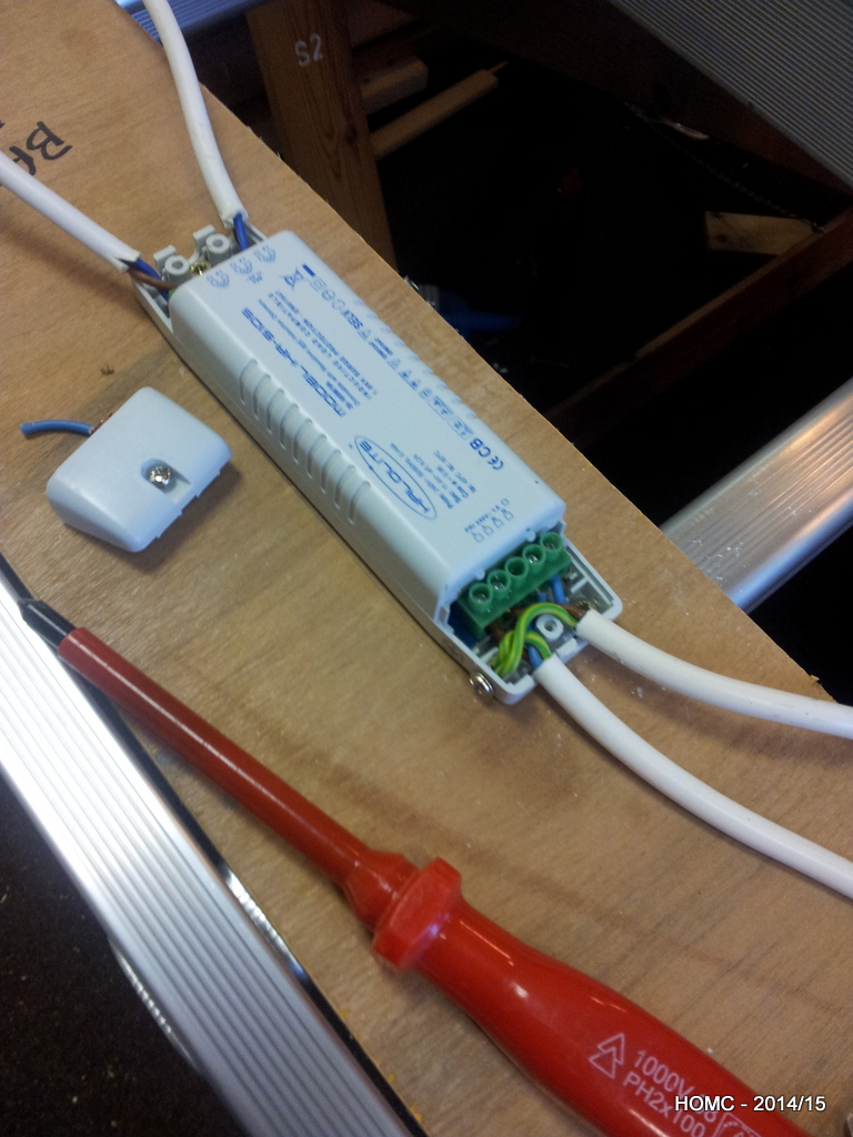
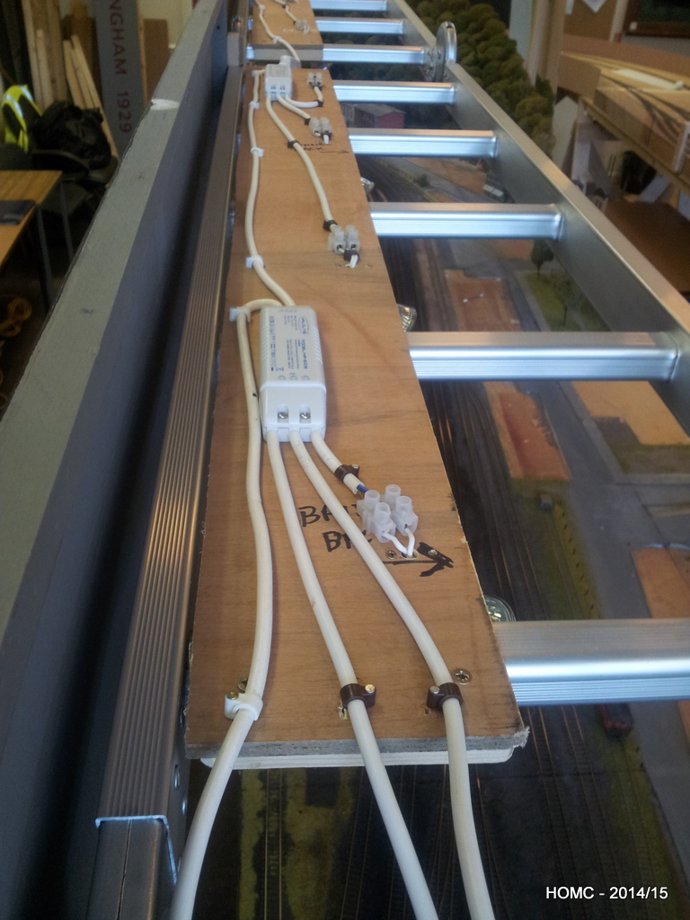
Lights are DC (12v) halogen, wide angle floods of 20, 35 and 50 watts. We attached these to the bottom of strips of plywood at 45 degree angles with basic lampholder bases. Along the top of each board were the transformers and the wiring. The plywood simply rests on top of the ladders and the fascia hangs off the front. A simple H frame at each end supports the ladder.
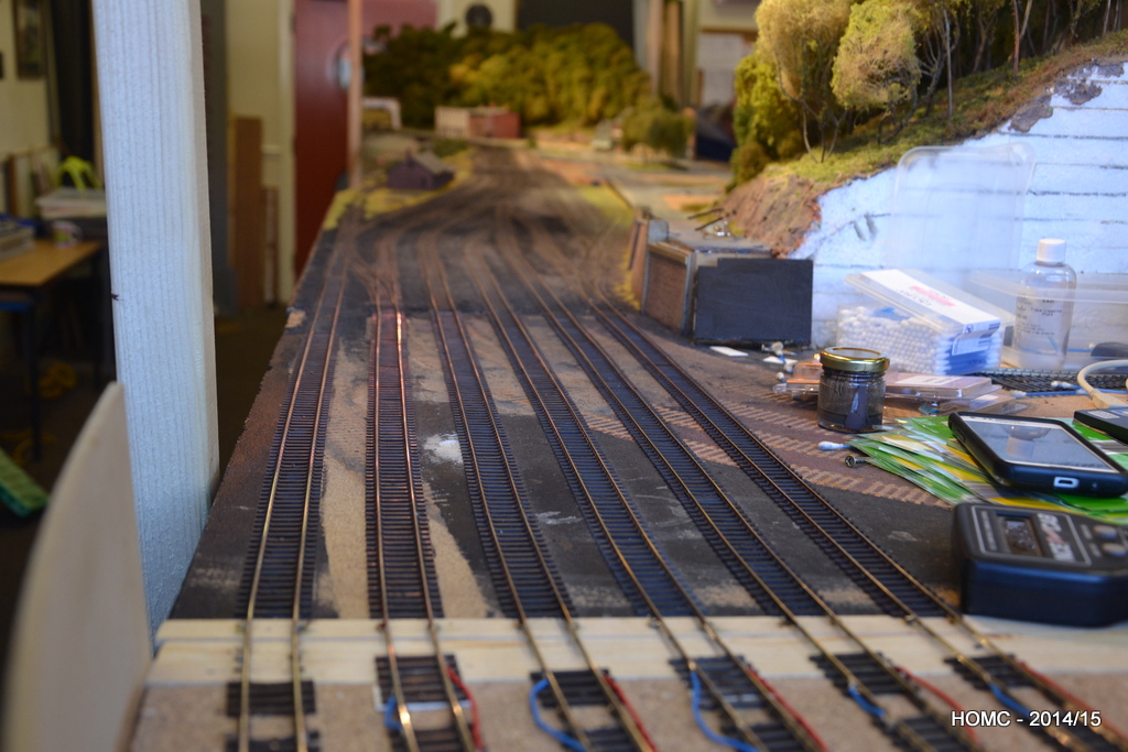
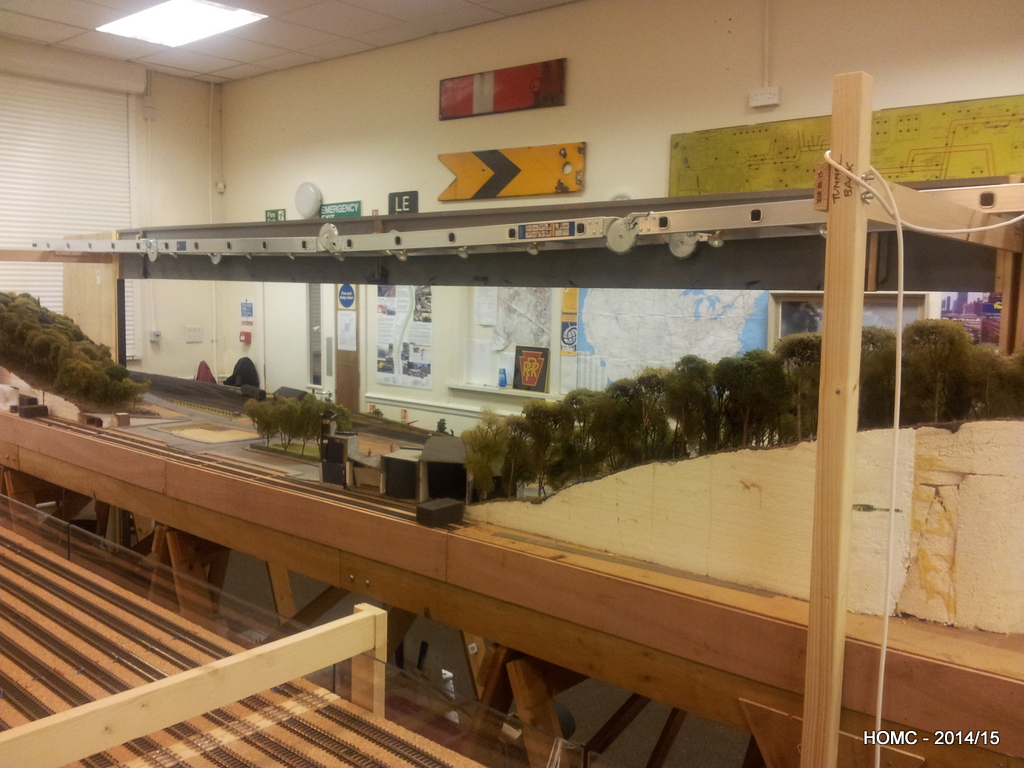
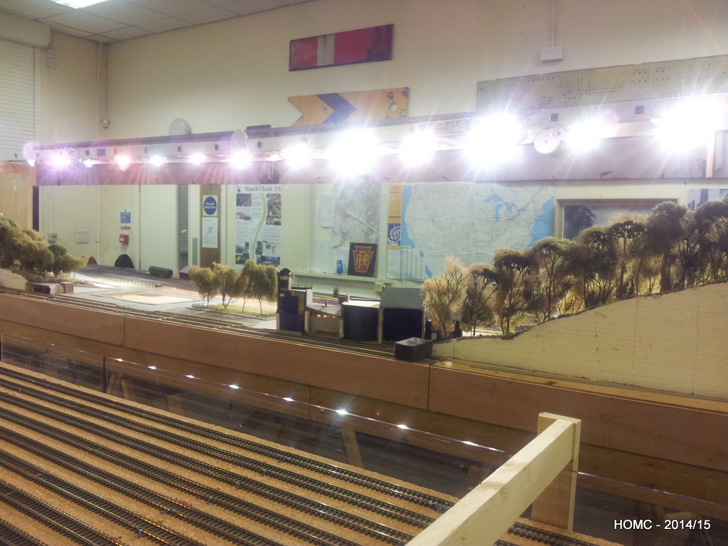
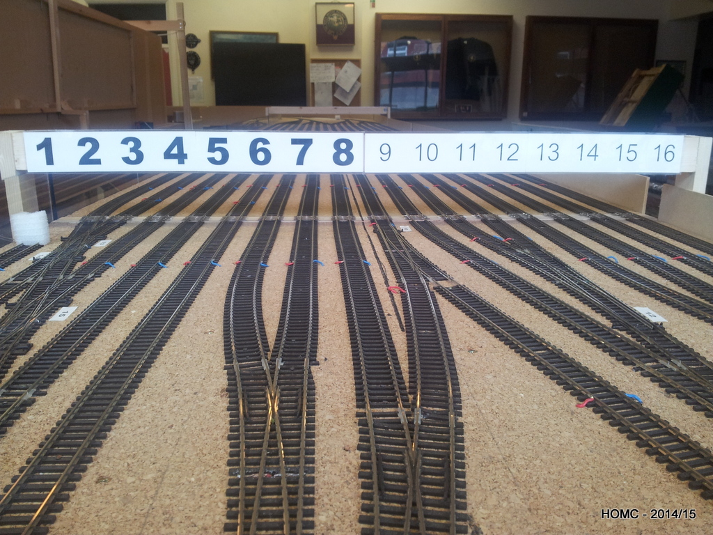
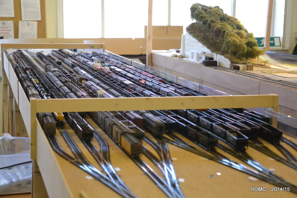
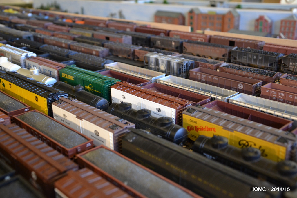
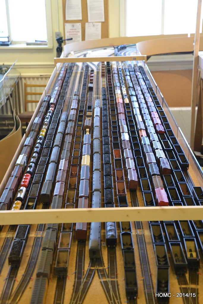
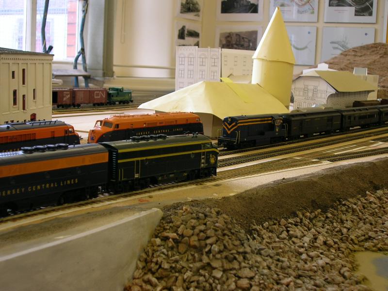
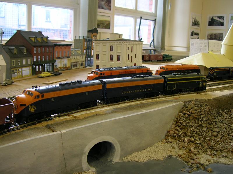
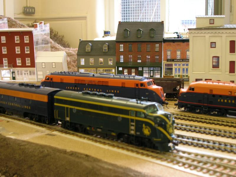
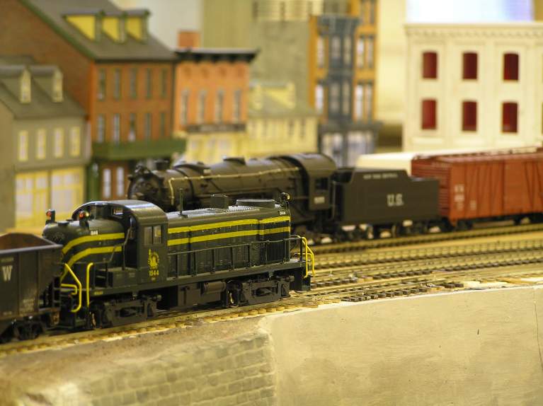
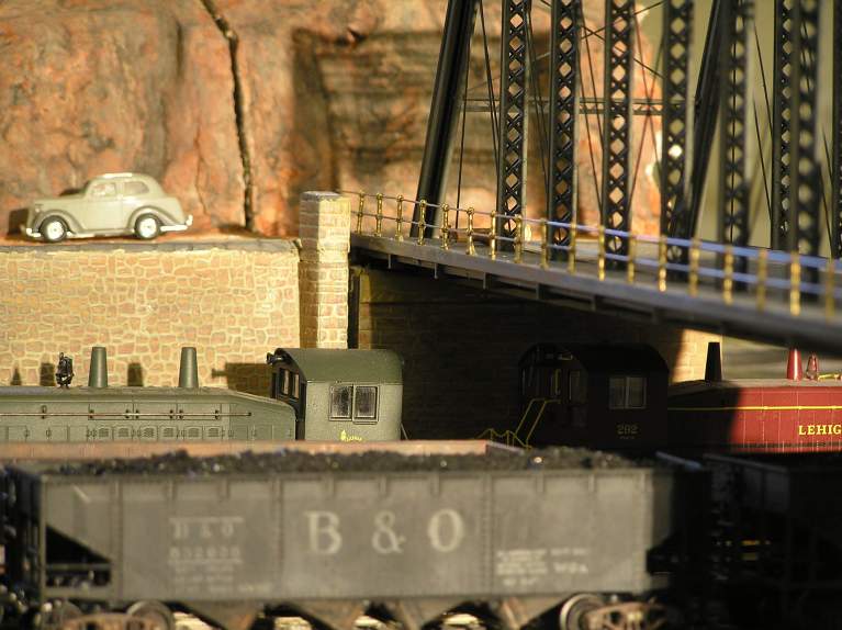
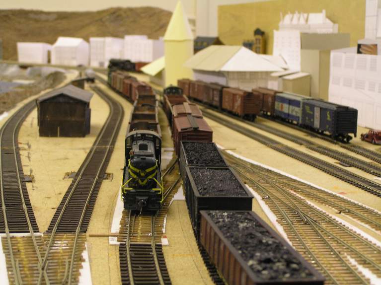
All this work completed, we decided to put our stock out on the staging yard and were quite shocked by how much we had – especially as most of our locos can’t pull such long trains. Still quite a lot of weathering, re-wheeling and Kadee-ing to be done though!
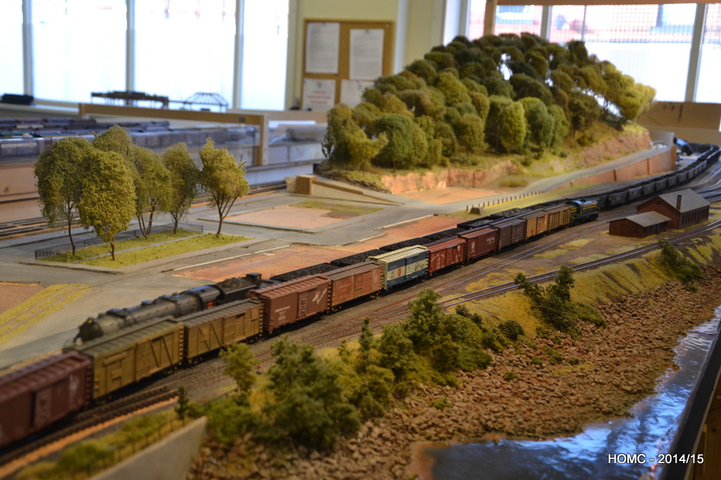
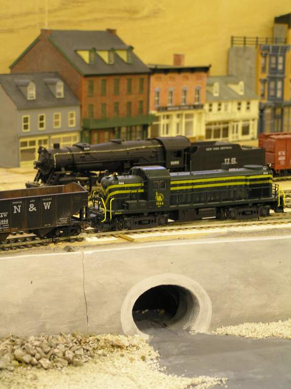
Finally a shot showing a consist of new (as yet undetailed) Athearn RS3s and then one with a N&W articulated interloper with a long empty coal train (note that the buildings have been removed for safe keeping). We are now moving on to add more hillside and roadway at the RH end, and then will work along adding detail to the scenery.
Despite my hopes that the updates to the site would become more regular after Gordon’s retirement in April and my continued life of leisure, what has actually happened is that we modelled at a high rate instead. As Doug is working a four day week, we modelled on Friday mornings as well and this made a big difference.
We had a good summer and used this to carry out repairs on our clubhouse – including demolishing a 120ft portacabin which also kept us pretty busy!
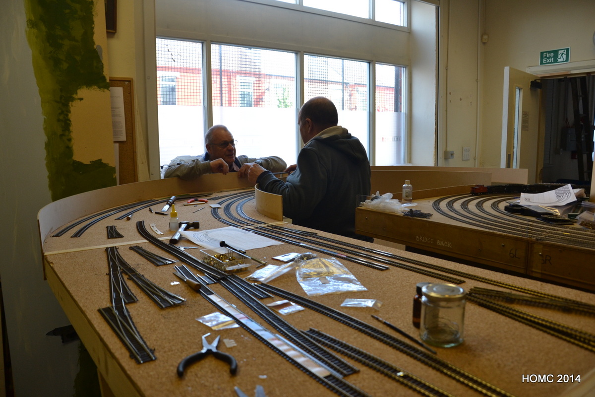
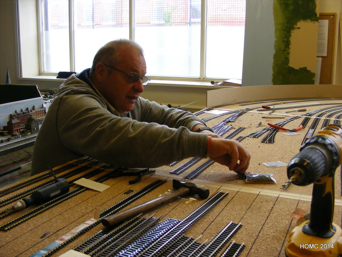
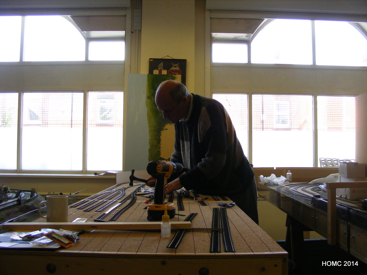
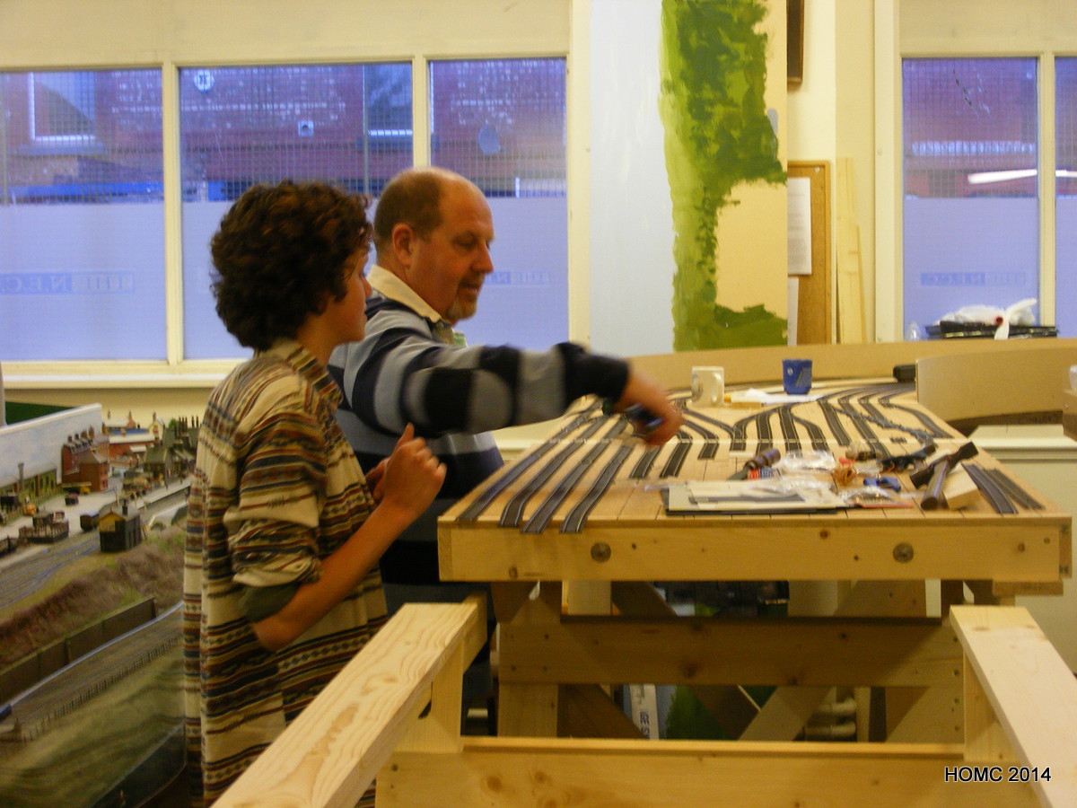
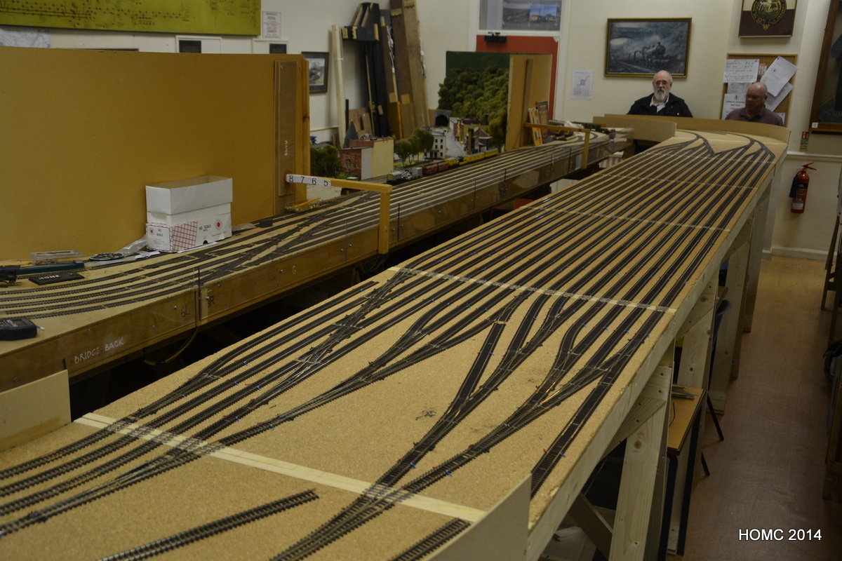
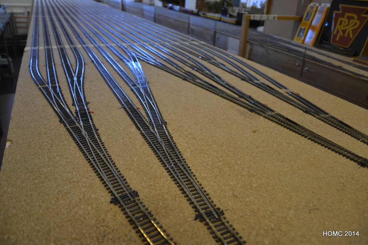
Here we are starting to lay track in the staging yard – if all else fails, hit it with a hammer! Even my daughter came in to lend a hand on a visit back from her midwifery course. The track laying progressed well. By August it had pretty much all been laid.
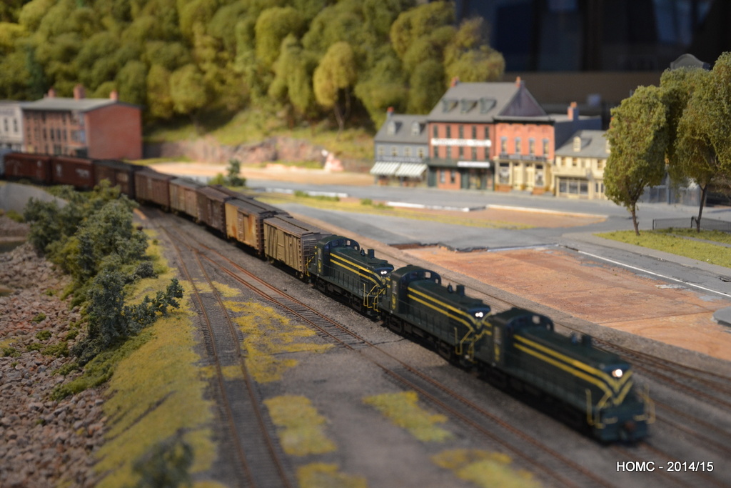
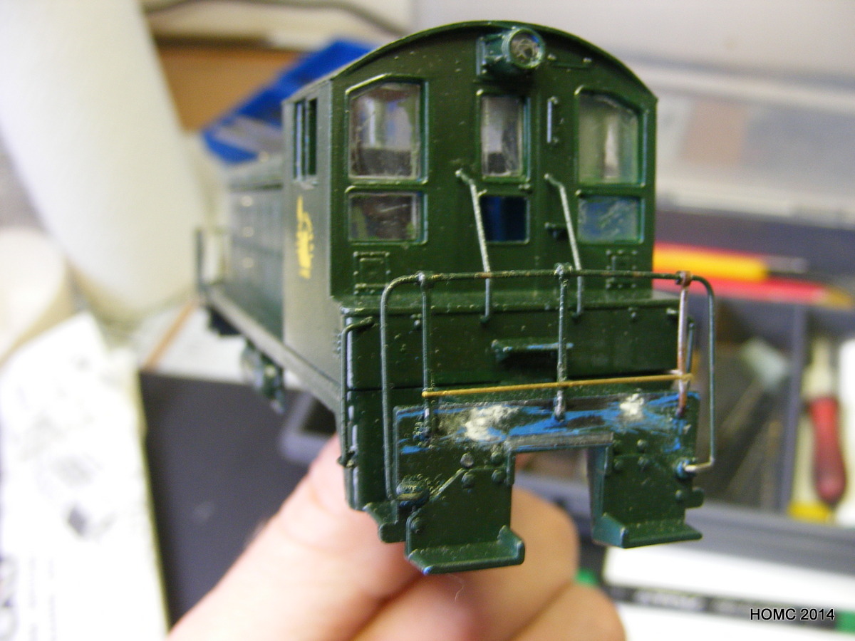
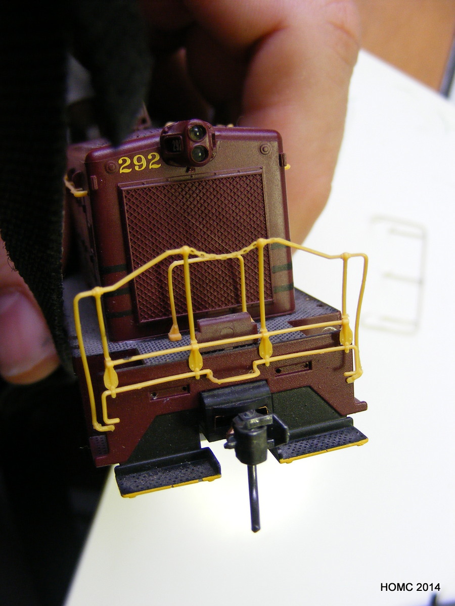
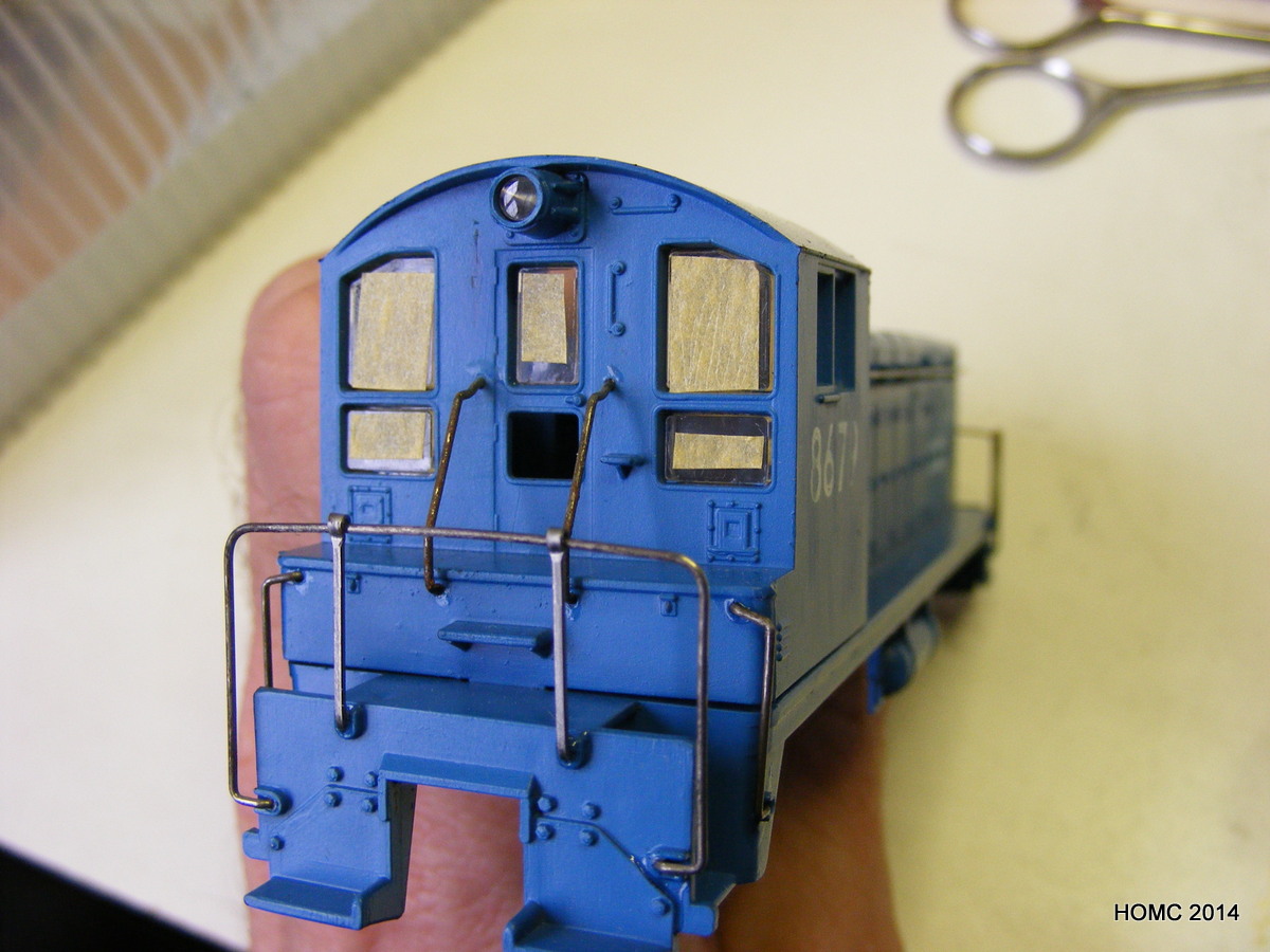
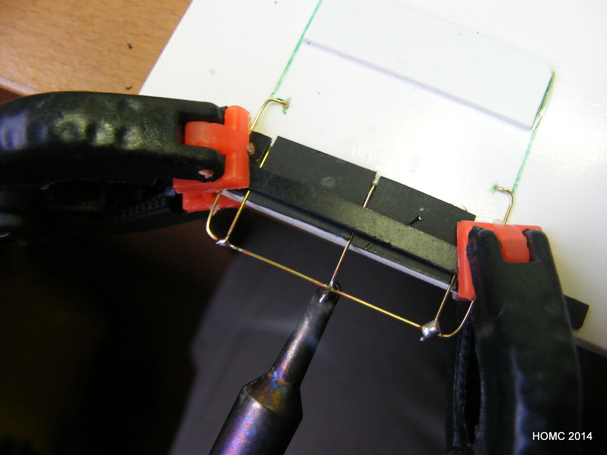
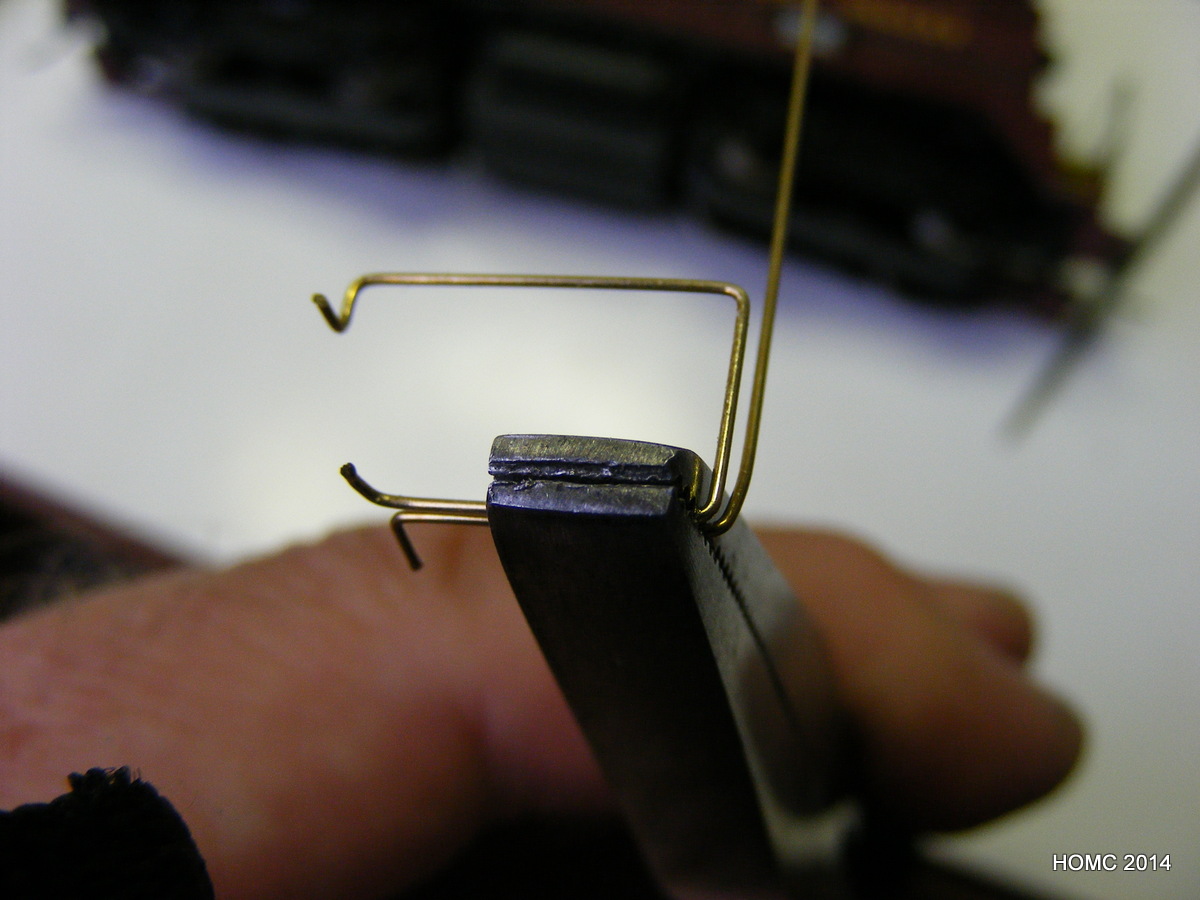
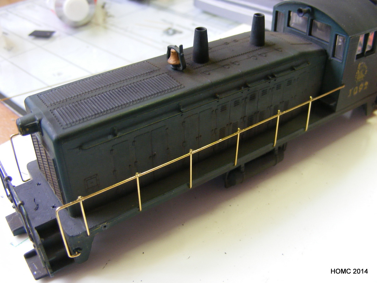
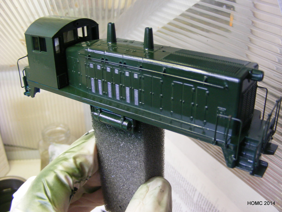
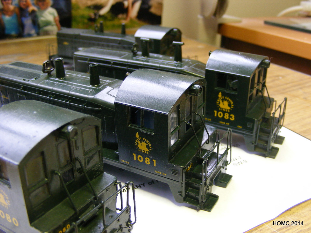
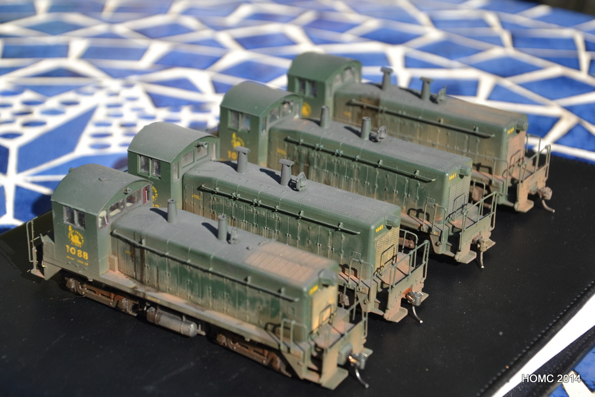
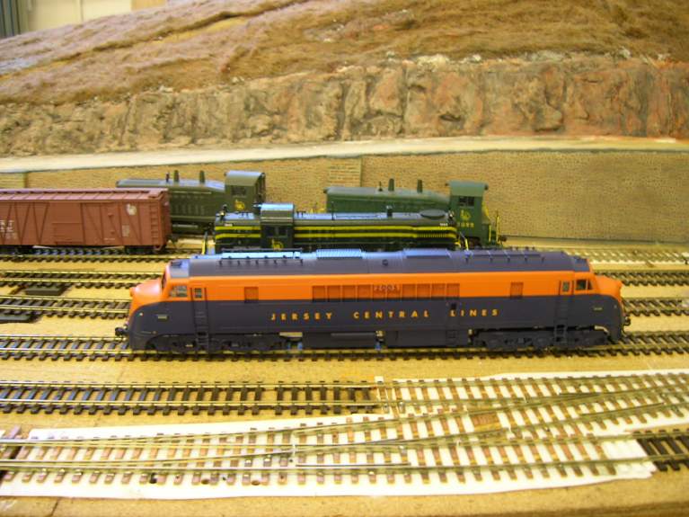
In the meanwhile, Steve was working on customising some SW7s and SW9s for the CNJ. Athearn and Proto-2000 stock was used as the starting point. Both jigs and hand bending were used to prepare the CNJ-style handrails – some were soldered, but most were superglued.
Handrails were added to different styles depending on the prototype, as were minor variation in the vent stacks. Once handrails (and some grab irons) were complete, the bodies were airbrushed with my own mixture of gloss green. RBH water slide decals were then applied carefully and the models were then sprayed with matt cote. Finally all were weathered with a mixture of techniques. Three were chipped and one set up as a dummy as not all the motors were usable.
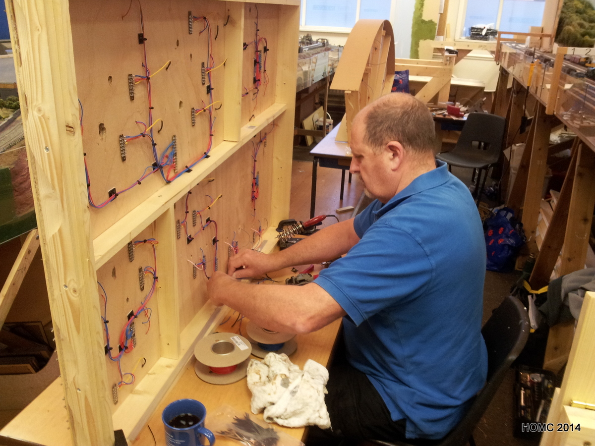
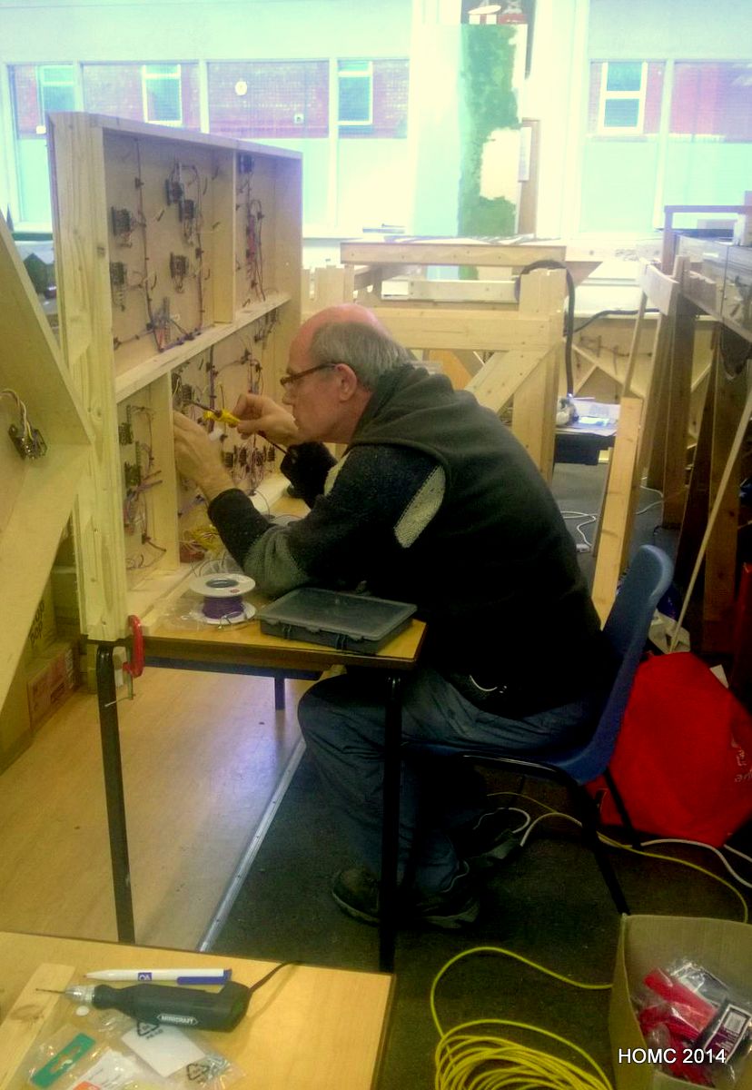
Meanwhile, back at the club, the hard work of wiring up the track and switches was proceeding – led by Doug, but with all three of us taking a share. Later, Doug withdrew from this exciting activity due to pressures of work and other interests, but we continued to fit and wire switch motors (Peco) with the help of Bill, and MERG DCC switch controller boards. These latter were mostly built by our club specialist (Derek) and wired in by Steve. Derek then configured them for us.
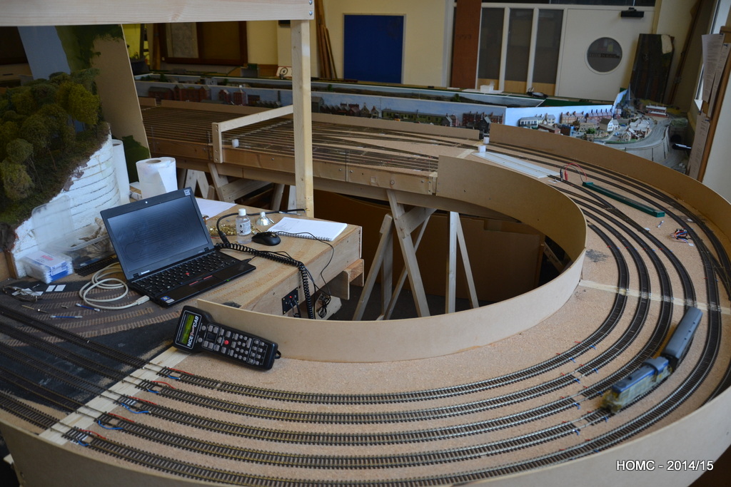
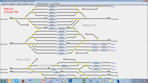
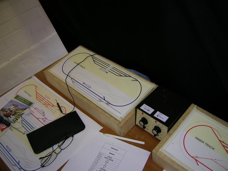
We set up computer control with the Big Bear software package – which works well. The track panel component (left) can be downloaded for free.
..and all the time the trains kept running round! We are now cutting and reconfiguring the old baseboards, removing the old staging yard, and hope to have finished this stage before Christmas.
As with last year we have made good progress in the first quarter – but it is again mostly invisible! Paul and Chris have just finished wiring the control panels for the switches and they work! We tried them out on the Open Day on Sunday 10th April and ran trains up and down all the tracks.
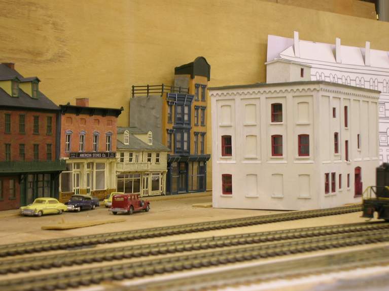
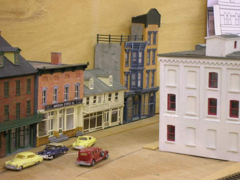
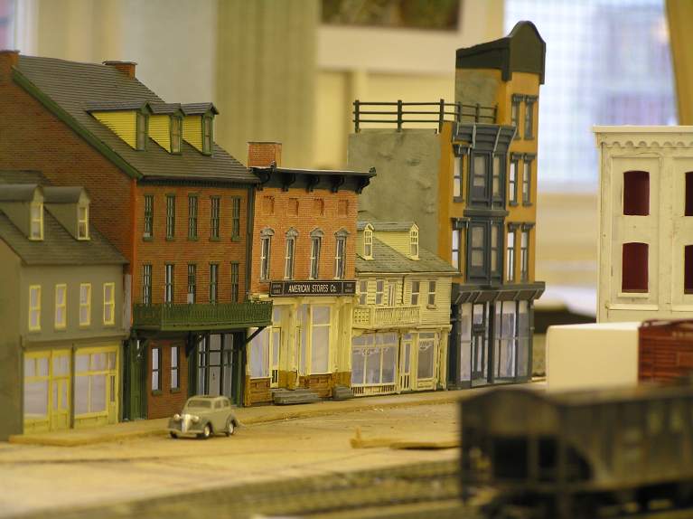
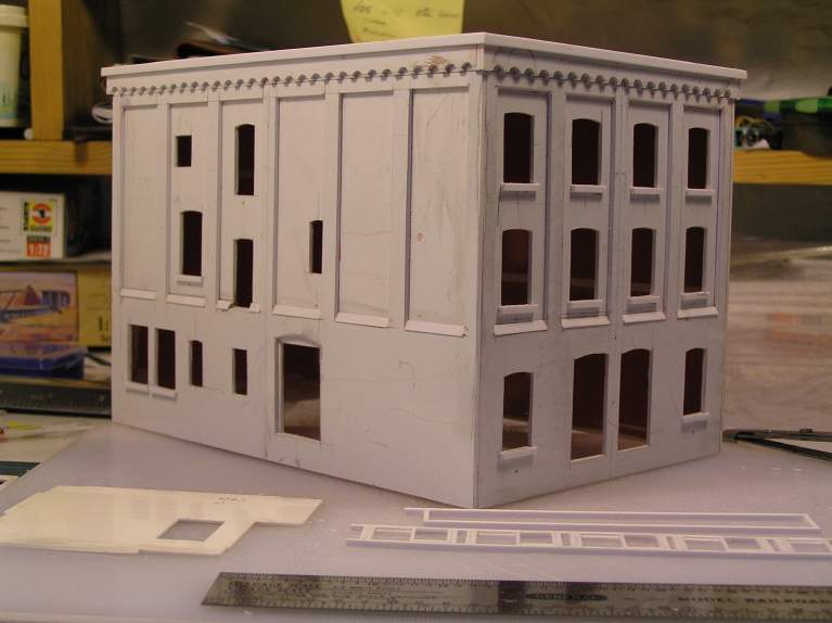
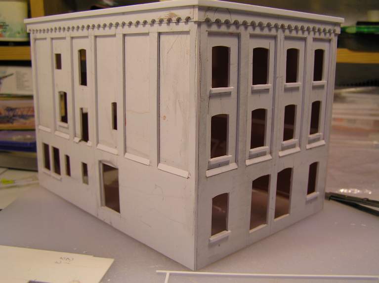
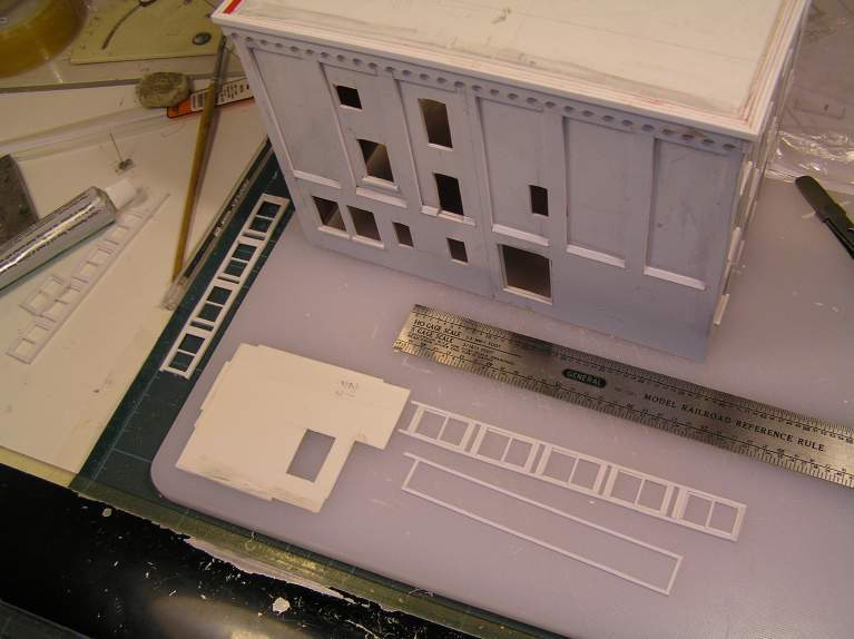
Steve is struggling with the sixth and seventh buildings on Susquehanna Street and Alisdair is working on the eighth. Ian is building the interiors and has so far completed two.
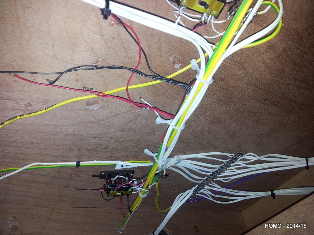
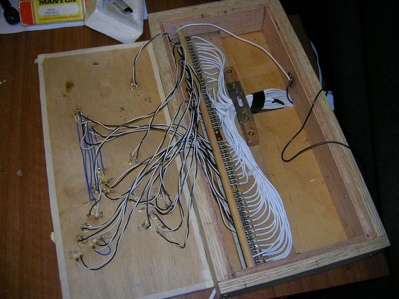
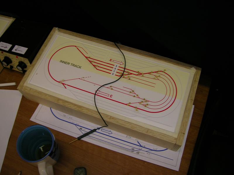
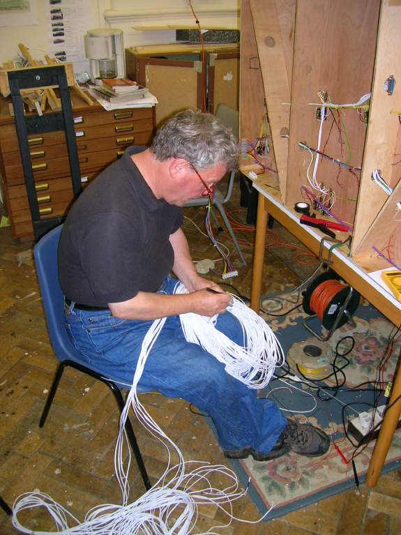
Again in the third quarter we have made good progress. Paul and Chris have now finished wiring the switches and switch motors on the front of the layout – and have now connected them up with looms of cable which will lead to two point control panels – one for each end of the layout. We intend to operate the layout with two operators, one at each end, and one controlling the eastbound tracks and one the westbound tracks. However, the wiring looms will be flexible to that both panels can go at one end, or a the back, or at the front. We’ll see what works best
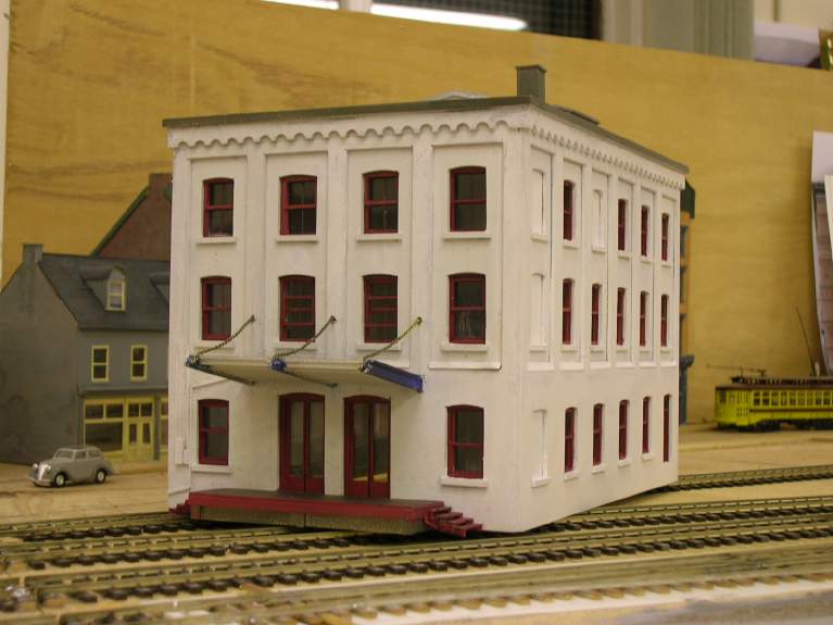
Chris has also nearly finished the Hooven Mercantile building – he’s even modelled the back. He only has to do the characteristic fire escape on the side to complete it and we have all the parts for that now.
Steve and Paul in particular are now spending a lot of time in preparation for the Merseyside exhibition at the end of October – we’ll put links in to the photos of that if you’re interested.
Photos include: Hooven Mercantile in all it’s glory – built by Chris (& us all relaxing).
Once again in the second quarter we are making good progress – once again it is mostly invisible! Paul with the help of Chris has continued to wire the switches and switch motors on the front of the layout – a tedious but essential job that has caused much debate!
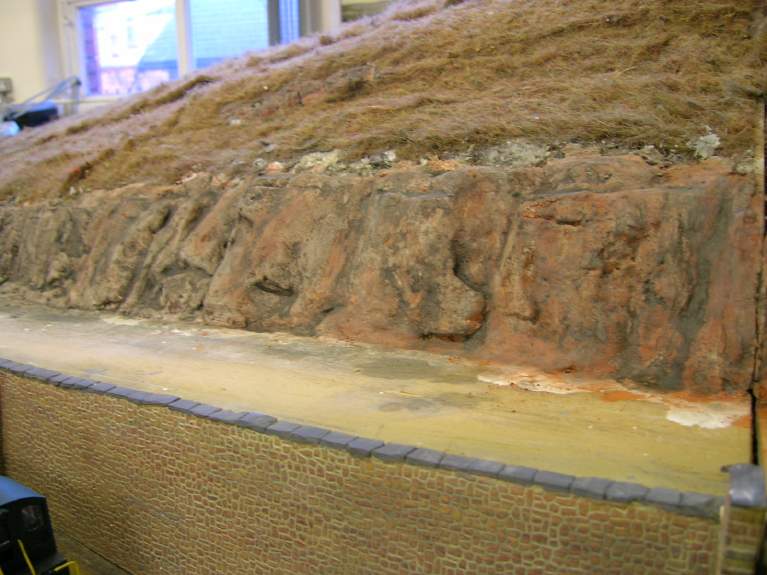
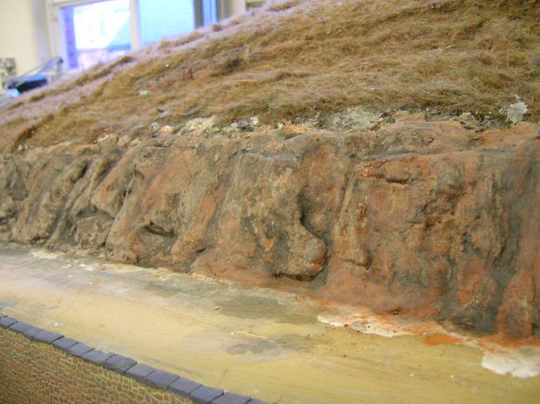
However, more has been going on – Steve has now built the fifth building on Susquehanna Street and Chris has started on the Hooven Mercantile building. Steve has continued with the rock face above the road on the RH side and has finished carving and painting and weathering it.
Photos include: Steve’s fifth buiding; Paul and Chris have been wiring up the switches; Chris has been building the Hooven Mercantile building like a true Architect (he is one); And the rock face – it will look better with vines and bushes, I expect.