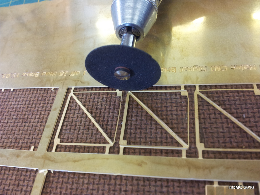
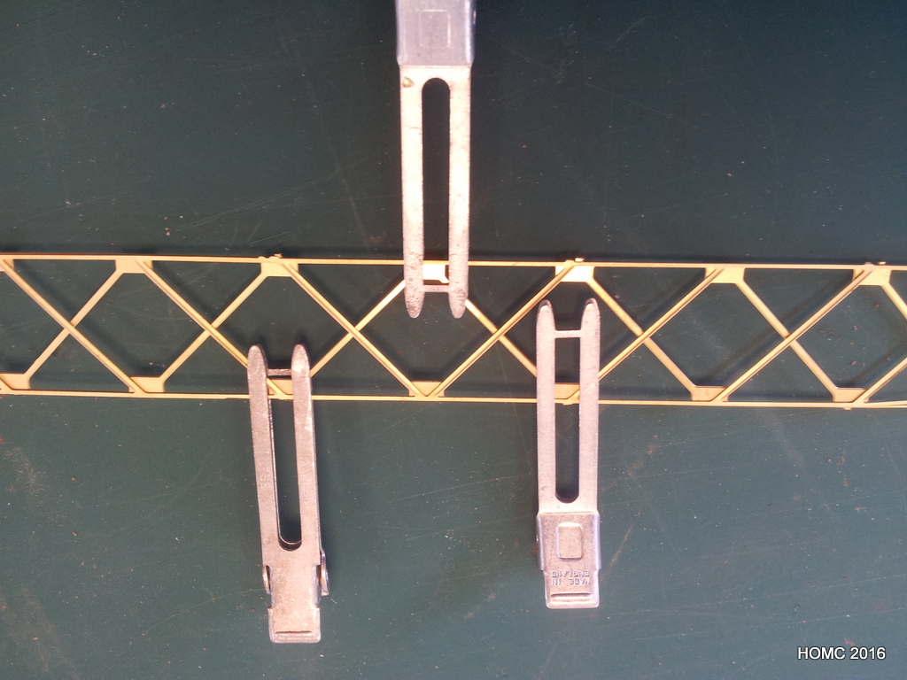
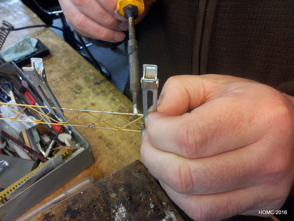
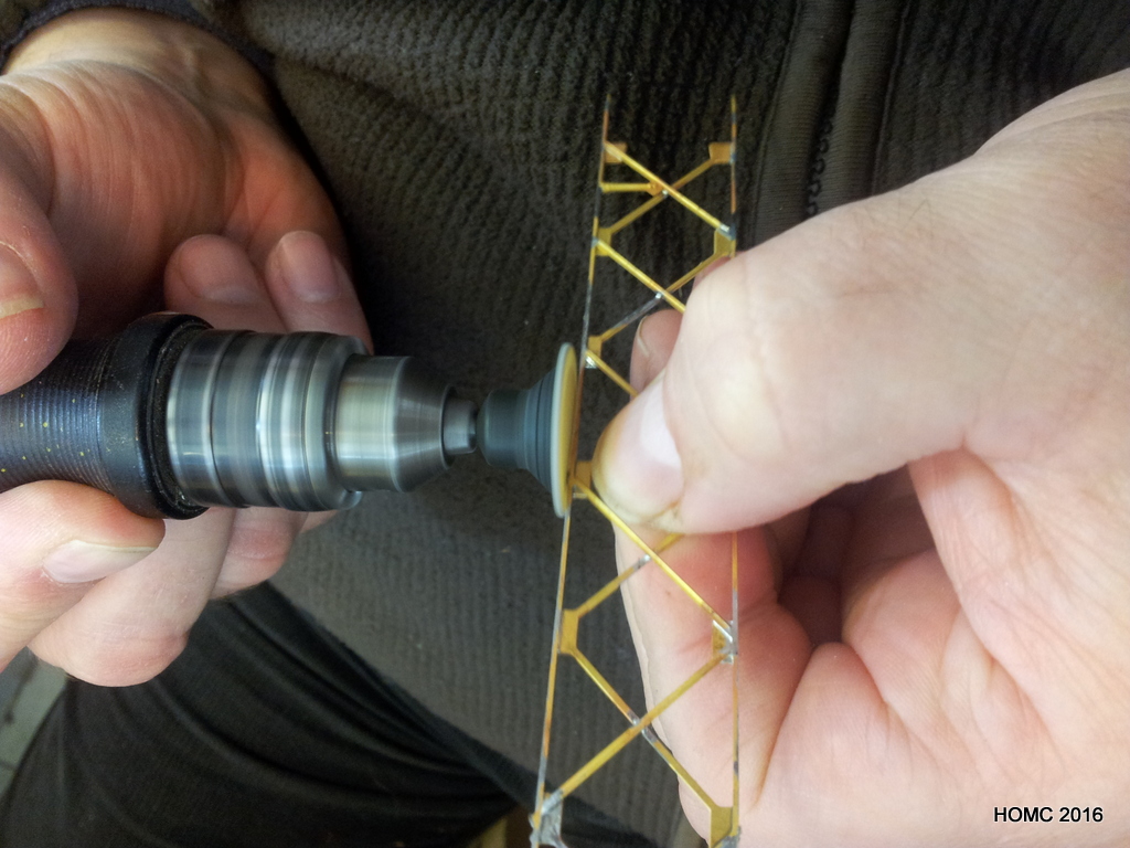
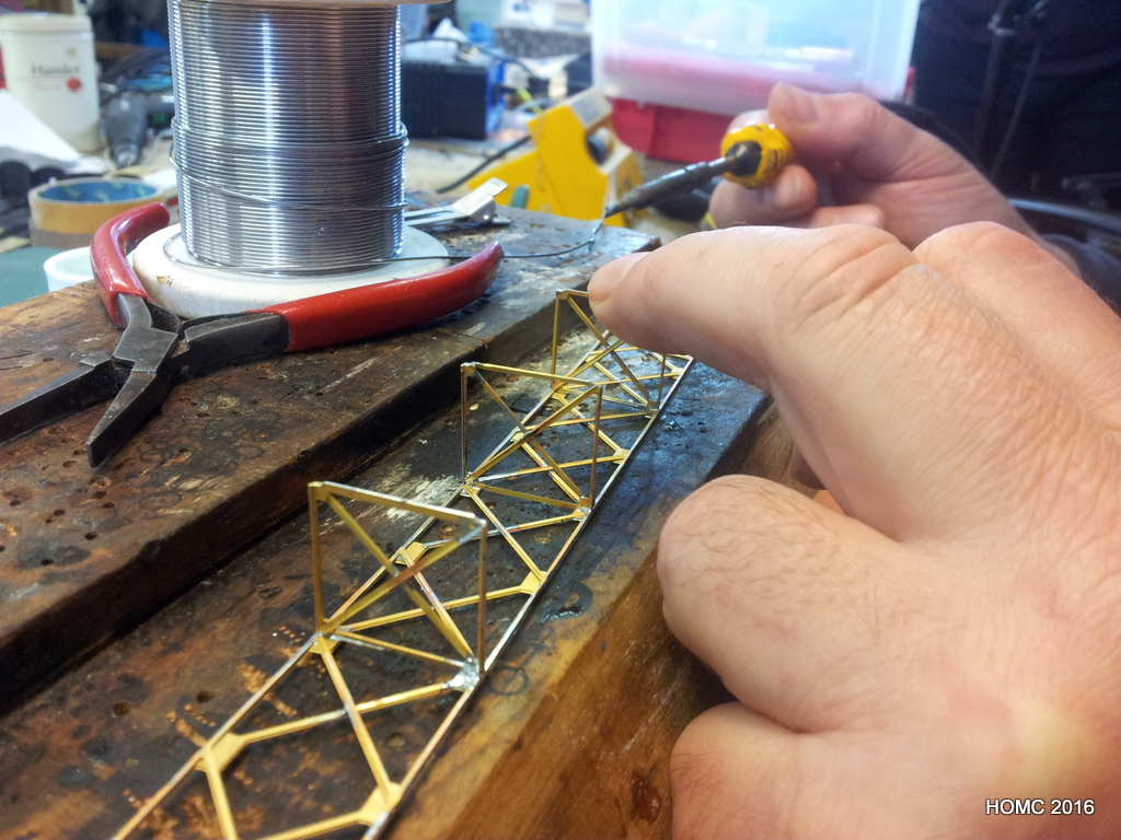
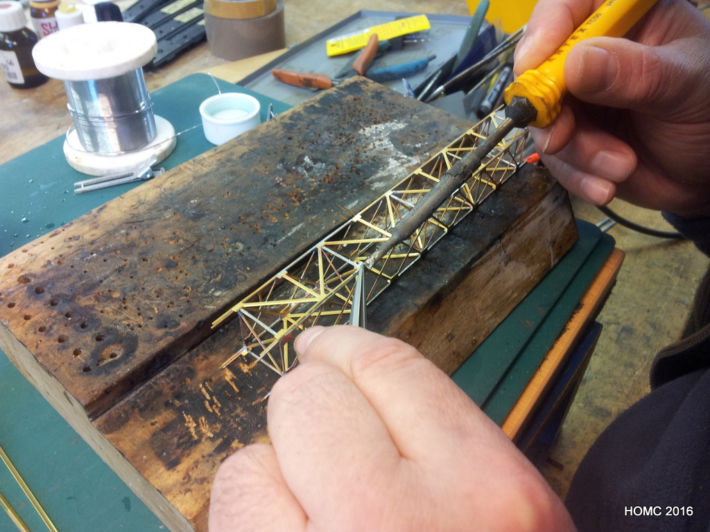
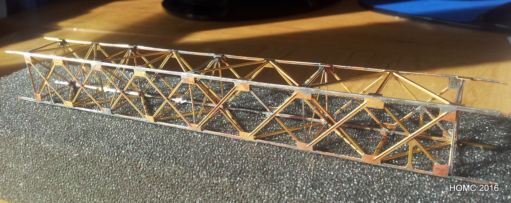
The signal bridge is only in prototype at the moment and the details below show a test etch of the gantry. This will be considerably modified for the final version. We are intending for this to be available in 2, 3 and 4 track versions for other CNJ and East Coast modellers – the details of how to do this have not been worked out yet, but don’t hesitate to contact us if you may be interested.


Author Archives: Steve Hales
Mikado kitbashes
At the Barrowmore club, work on the Mikados was carried out by Steve, starting with the kitbashes originally worked on by the (late) Chris Bennett and Steve. The full details of the assembly will be placed in a project page, but in the meanwhile, please download the full instructions as a pdf here. Here are a few photos from the construction:


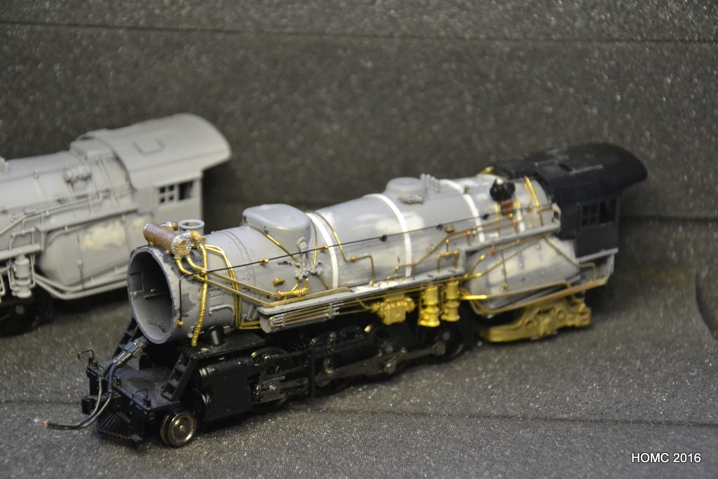


In this final photo a complete kitbash sits in front of a BLI brass equivalent.
Baseboard Trolleys
This last six or so months has seen Gordon and I finishing the trolleys, checking they fit in a Luton van (as we will use to transport them to exhibition) and finishing work on the BLI USRA Mikado conversions to CNJ M3 Miikados. A lot of hopper cars have also been completed, ready now to be weathered and loaded. Finally, work is now starting on building a working signal gantry for the west end of the layout.
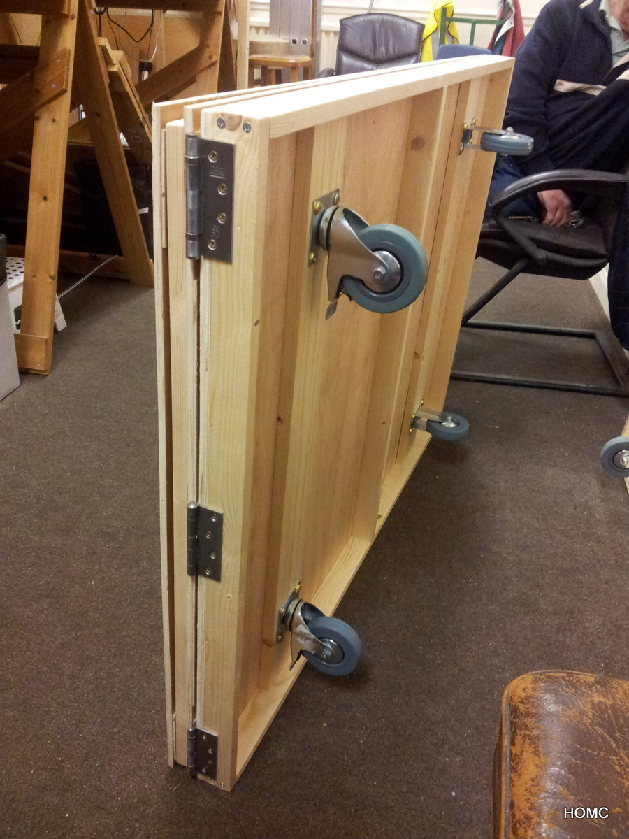
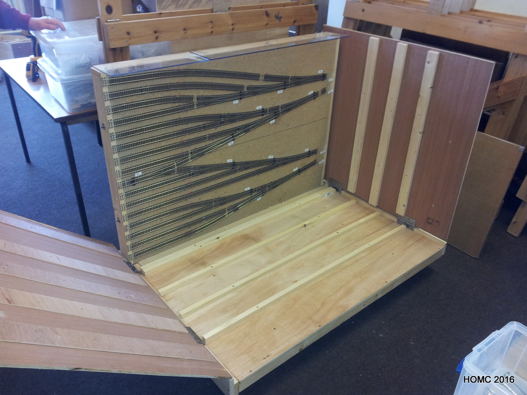
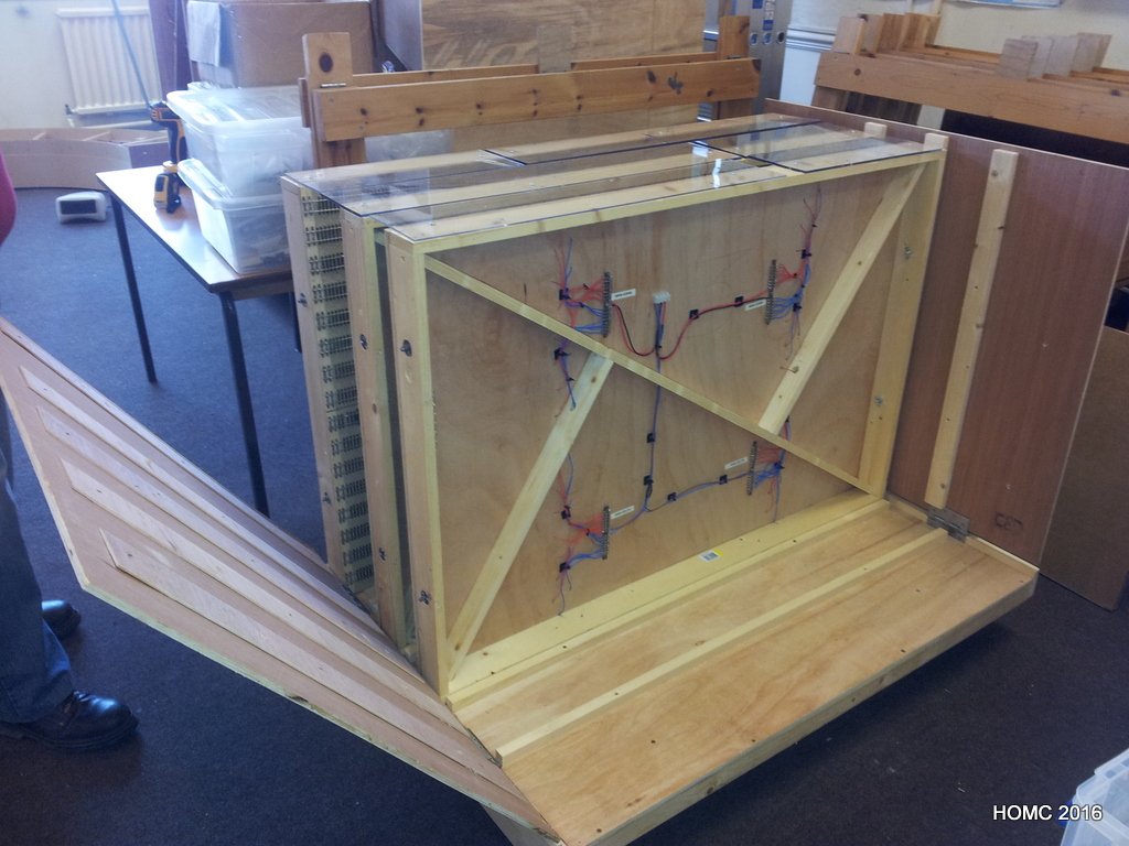
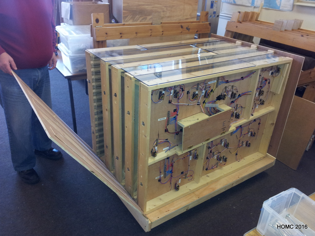
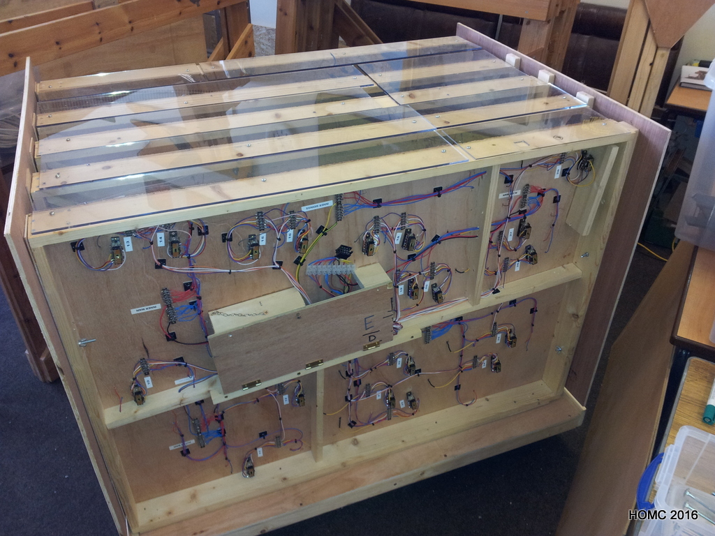
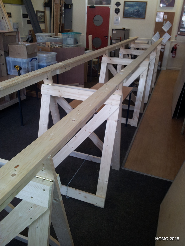
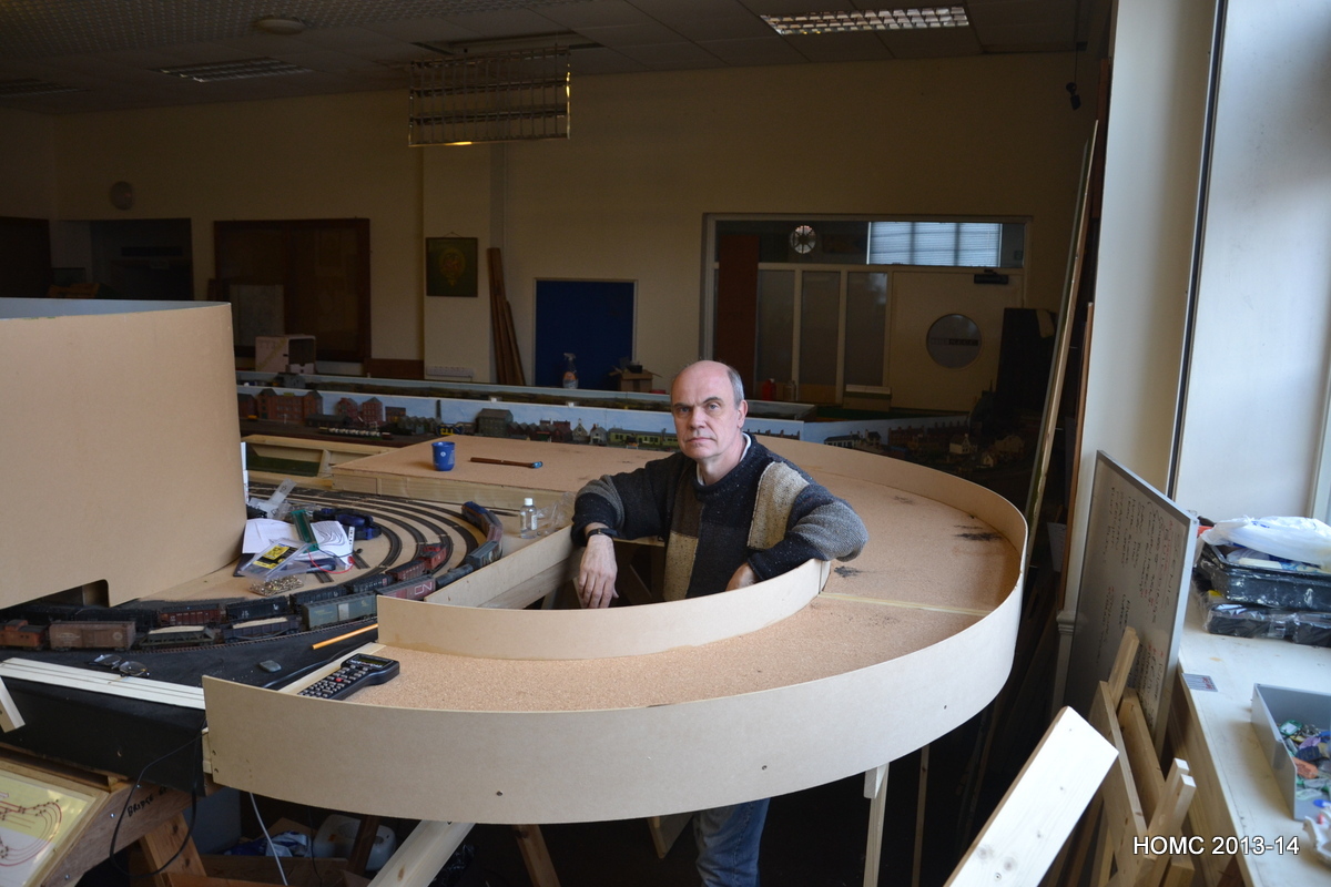
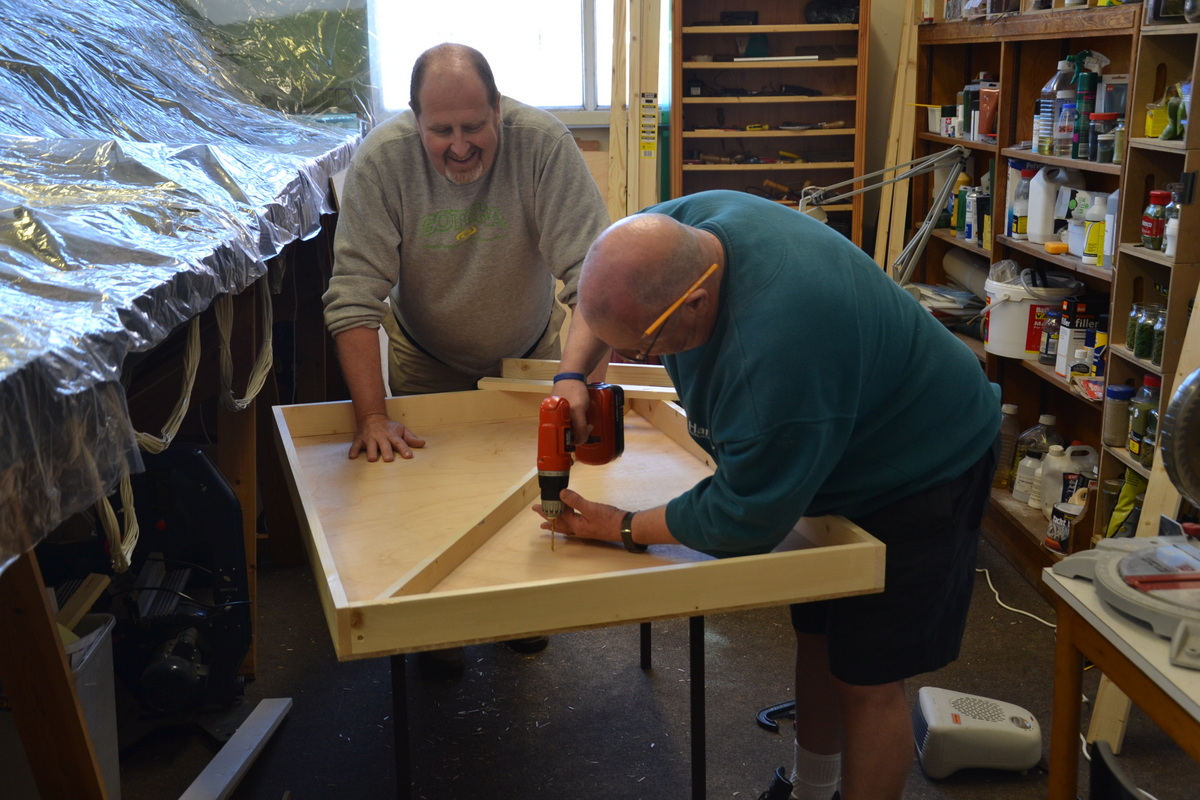
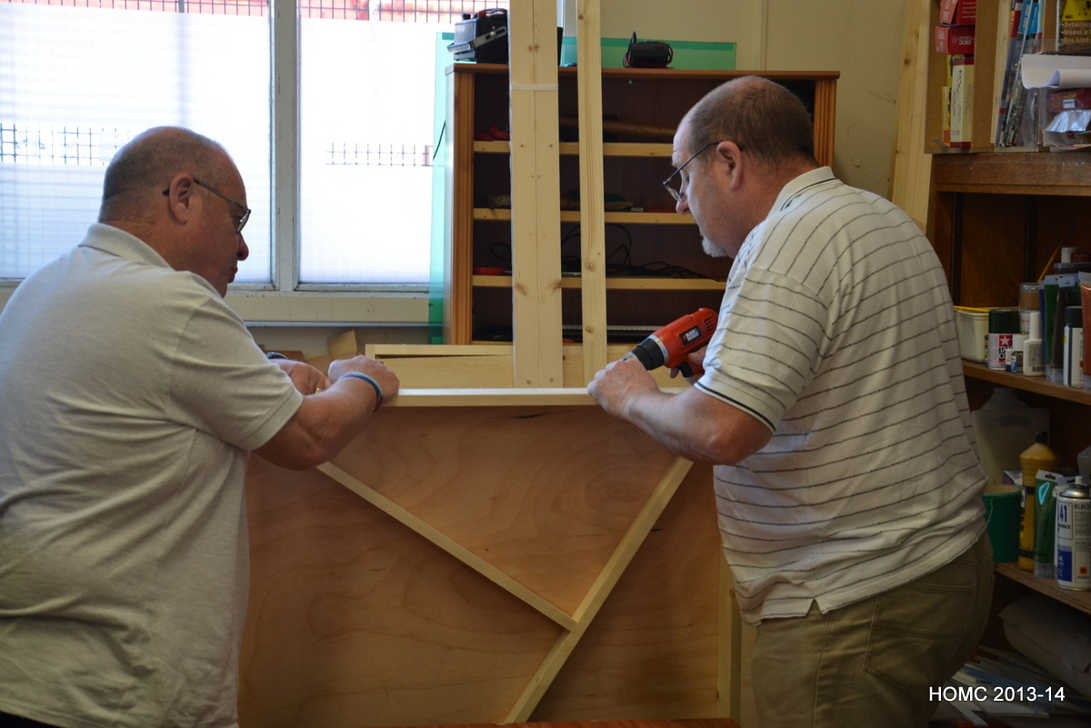
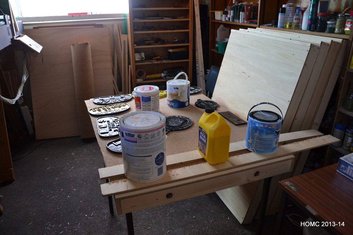
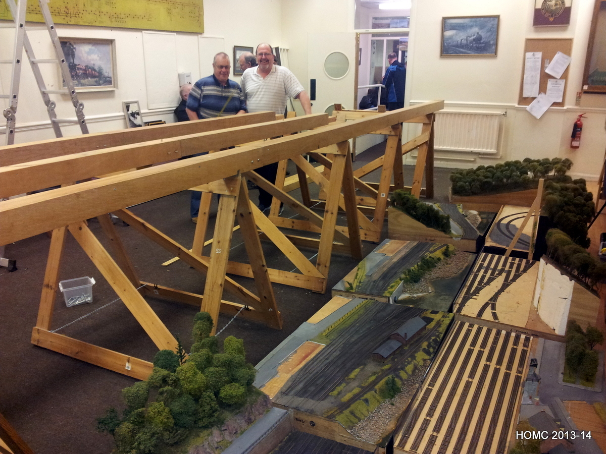
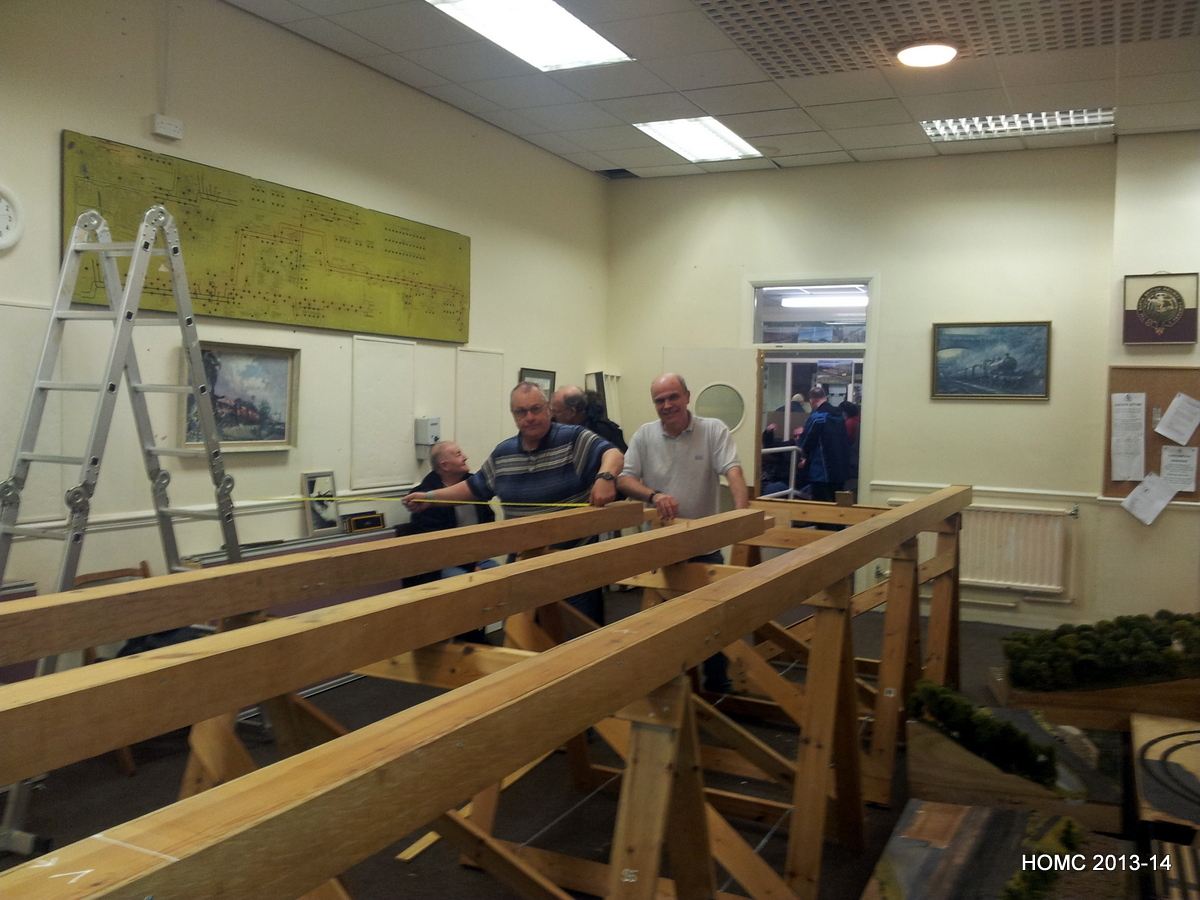
These first five photos show the trolley purpose built for the storage yard. All five 3ft x 4ft boards fit into grooves in it and when the ends are both closed, are secure for transport. The unloaded trolley folds up into a small space – first photo.
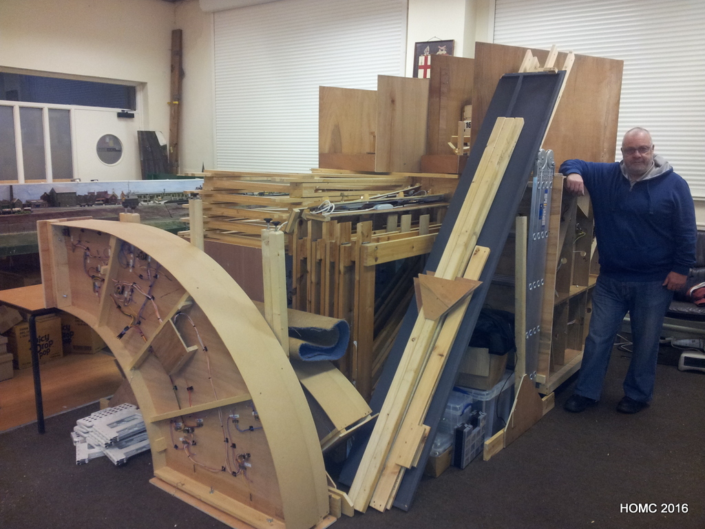
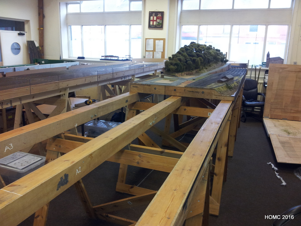
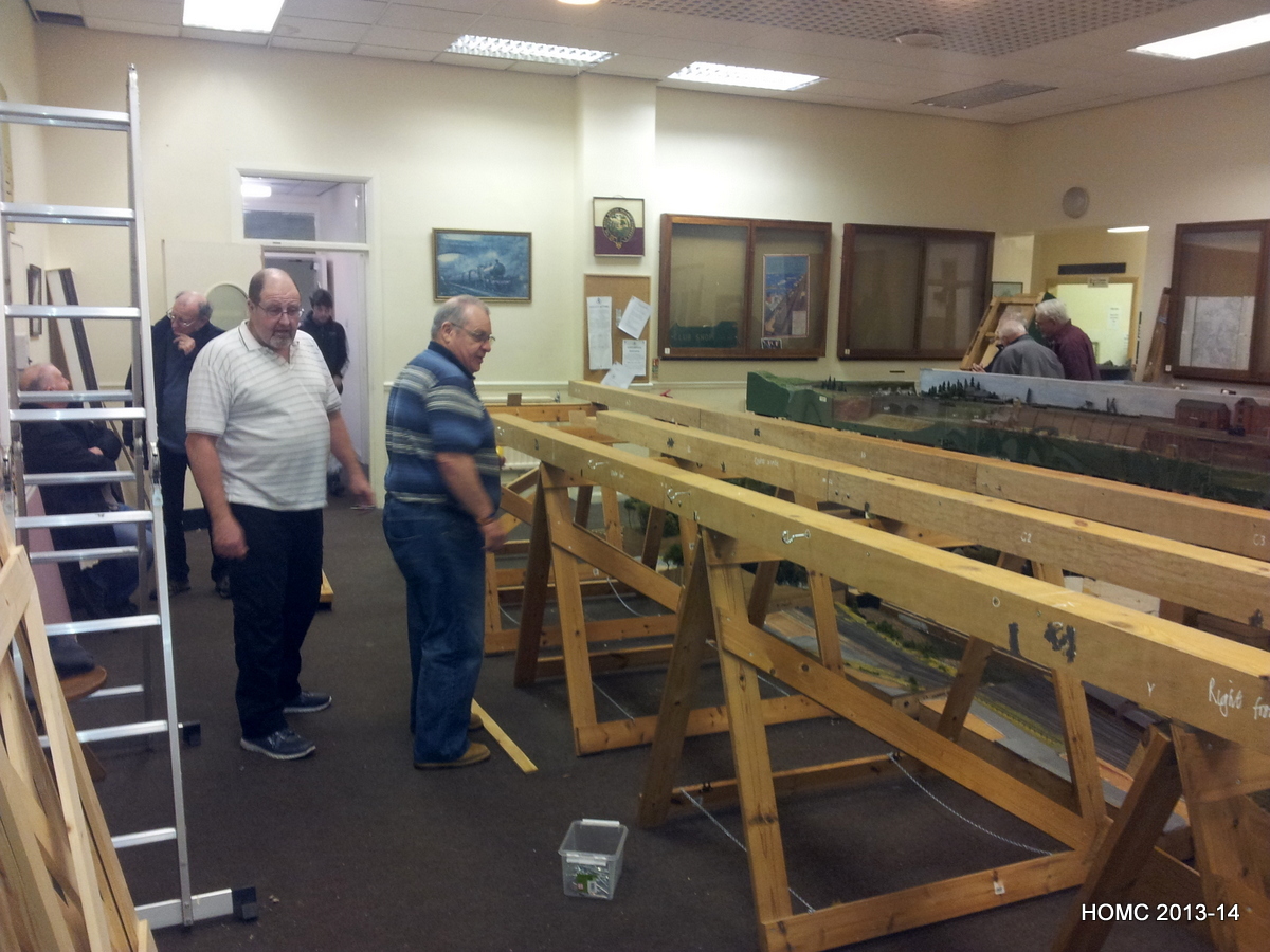
Once all the scenic and storage yards boards are packed into their trolleys and, the end boards are folded into each other, they were stacked into a space the size of a Luton van to make sure we could transport the layout to exhibition. Here are two photos showing the ‘stacked van’! Not very exciting but very important. Finally we reassembled the layout in a couple of hours (well, almost).


Stock & Trolleys
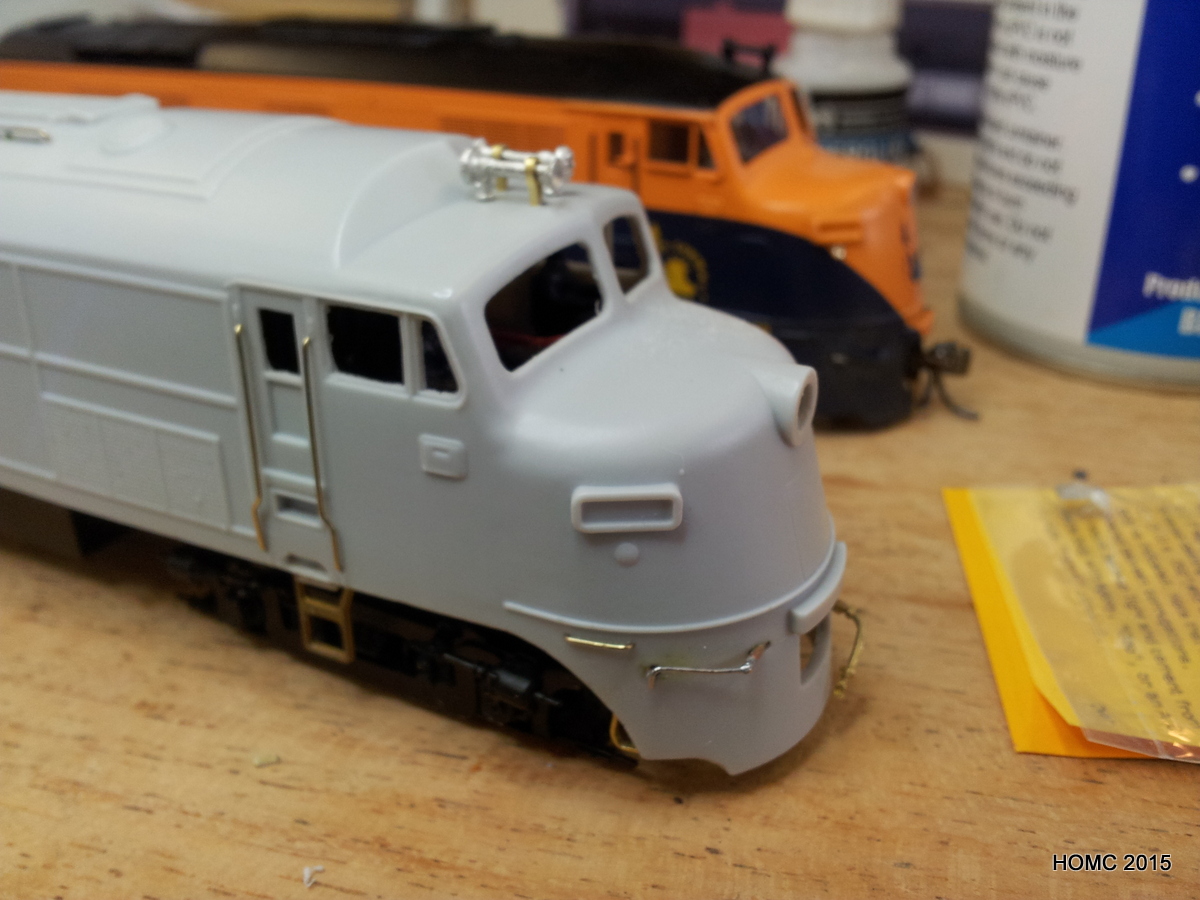
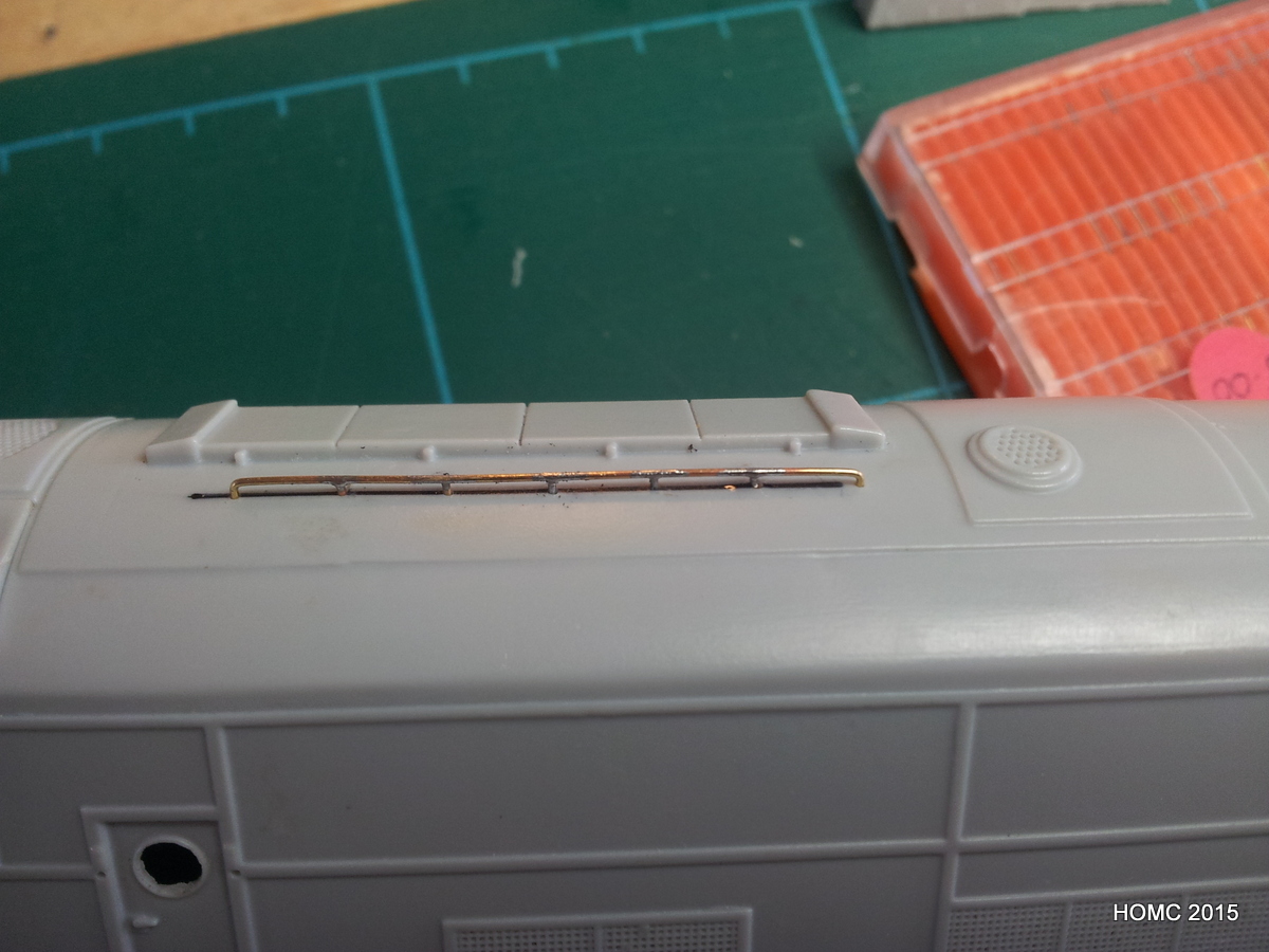
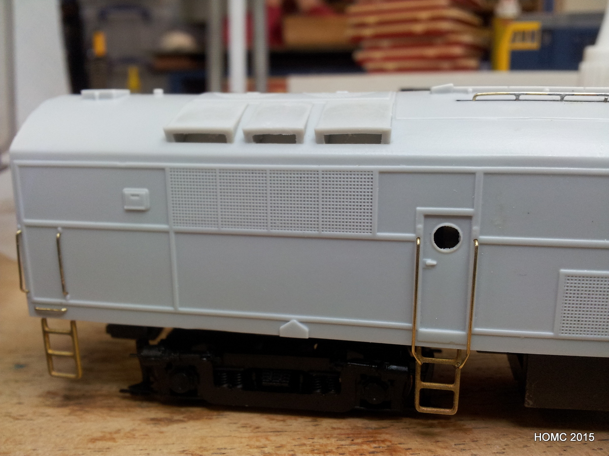
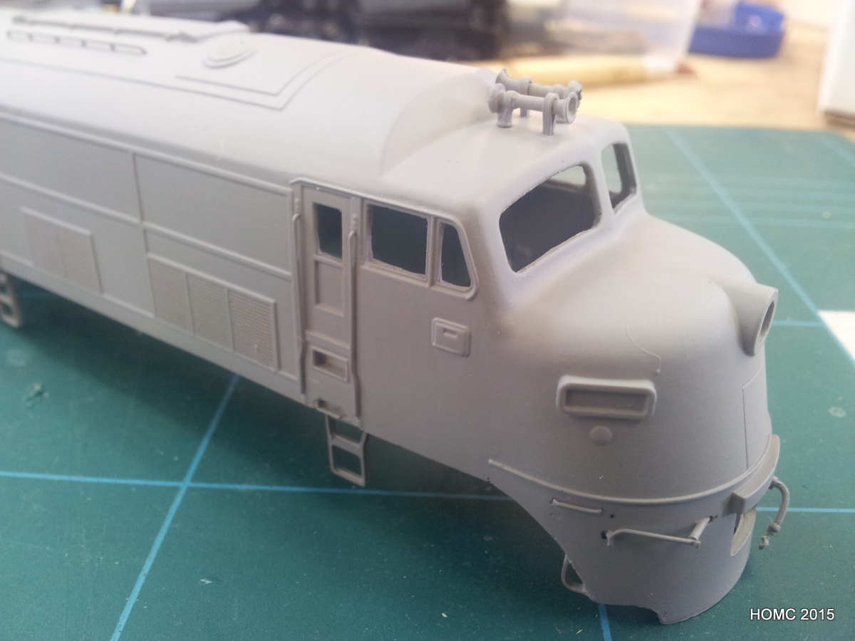
Another result of this resolution was a visit by Steve to the local Barrowmore Model Railway Group, which turned into a membership there. The BMRG is way ahead of the Merseyside club in stock building and Steve’s first project there was to build the ARHS Babyface A-B-A set that were sitting in boxes in a cupboard. This was mainly a case of adding grab irons and other ironwork. The most complex piece was a roof rail, which was build by Richard Oldfield. The final shot shows the effect of priming ready for painting – which will be done in the new year. I should comment that fitting the recommended underframe from Proto 2000 Alco FA2s into these bodyshells required a lot of grinding away of the weight and also the insides of the bodyshell. One of the bodyshells was so thin in one spot, that it blistered when painted, and has to be rebuild with plasticard and superglue. However, these little obstacle are to be expected when kitbashing and building!
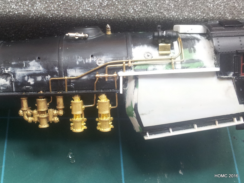
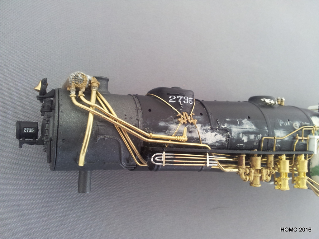
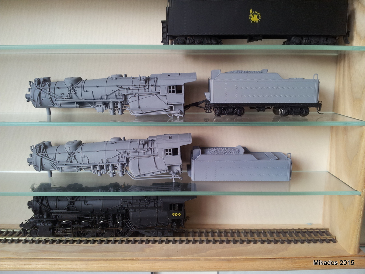
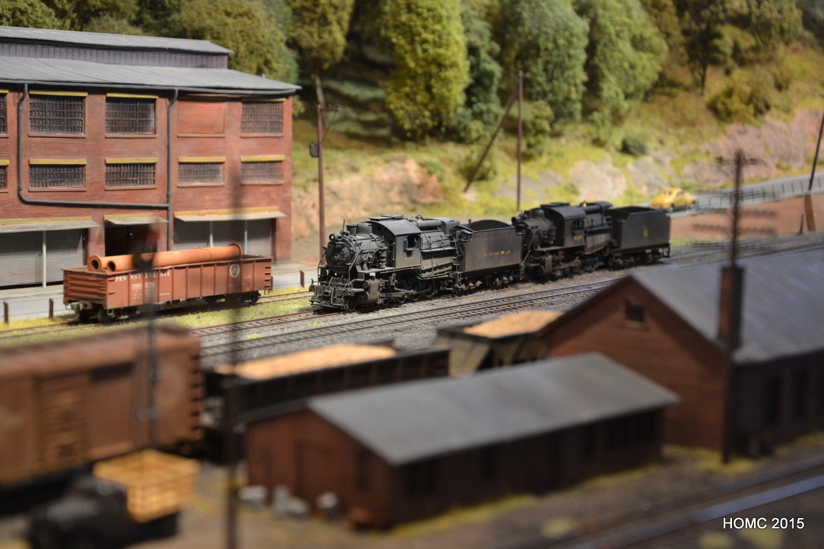
Steve then moved on to kitbashes of two M3 Mikados from BLI USRA Mikados – a project started several years ago with the late Chirs Bennett. This is now nearing completion and will appear on the project page once finished! Just one photo as an appetiser – the complete model at the bottom of the shot is an Overland brass M3s.
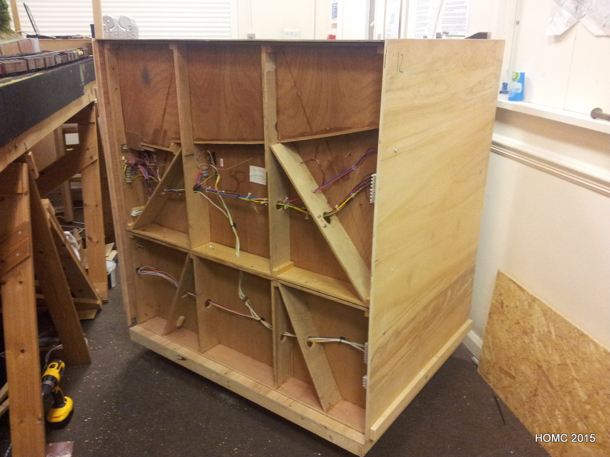
Meanwhile, back at the Merseyside club, construction of three trolleys was underway by Gordon and Steve: The new 4ft by 4ft baseboards are so heavy that they cannot realistically be carried any distance as when moving them to an exhibition. Therefore plywood trolleys are being built that can be wheeled from the clubhouse into a van (with a tail lift) and then from the van into the exhibition hall on arrival. Two of the trolleys each take two front boards, and the third takes all five staging yard board. This last is still under construction, but the first two are now complete.


November 2015 – layout
This last 8 or nine months has seen us tidying up from the extension on the scenic boards, building some trolleys, starting work on locomotive kitbashes and finally, hosting a visit from an American visitor!
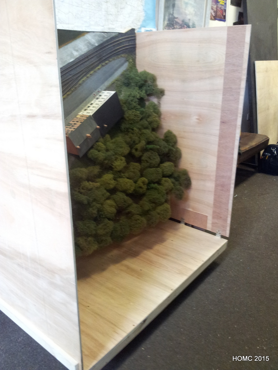
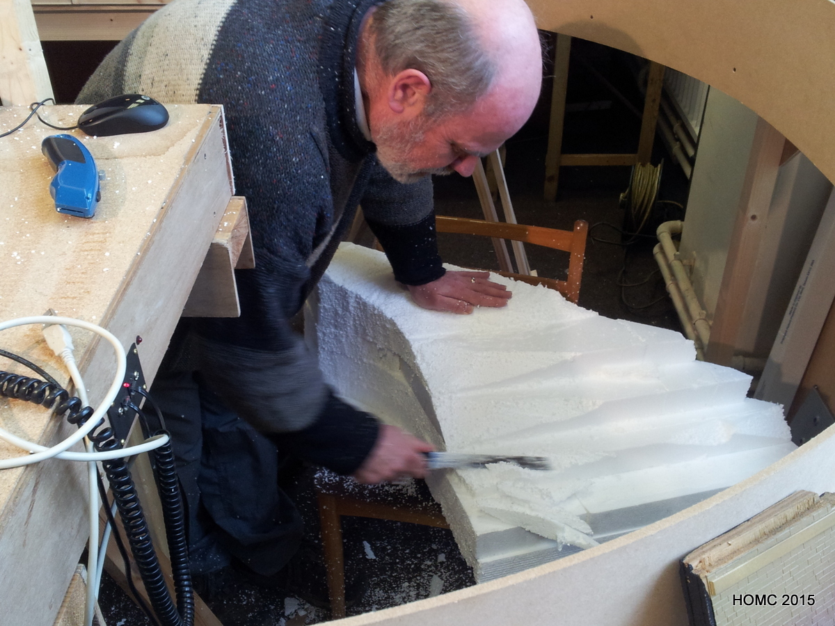
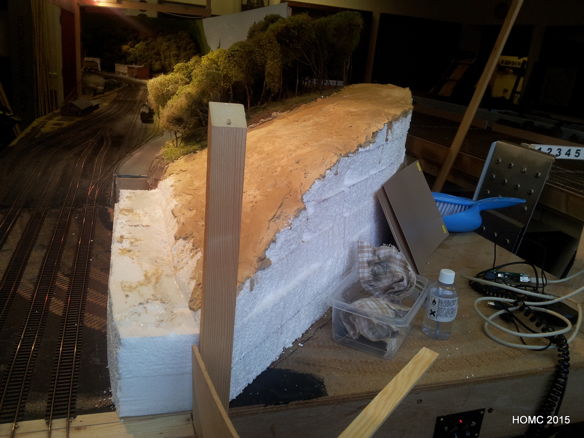
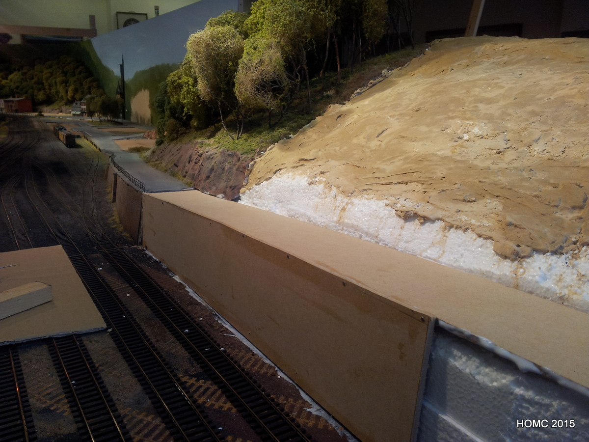
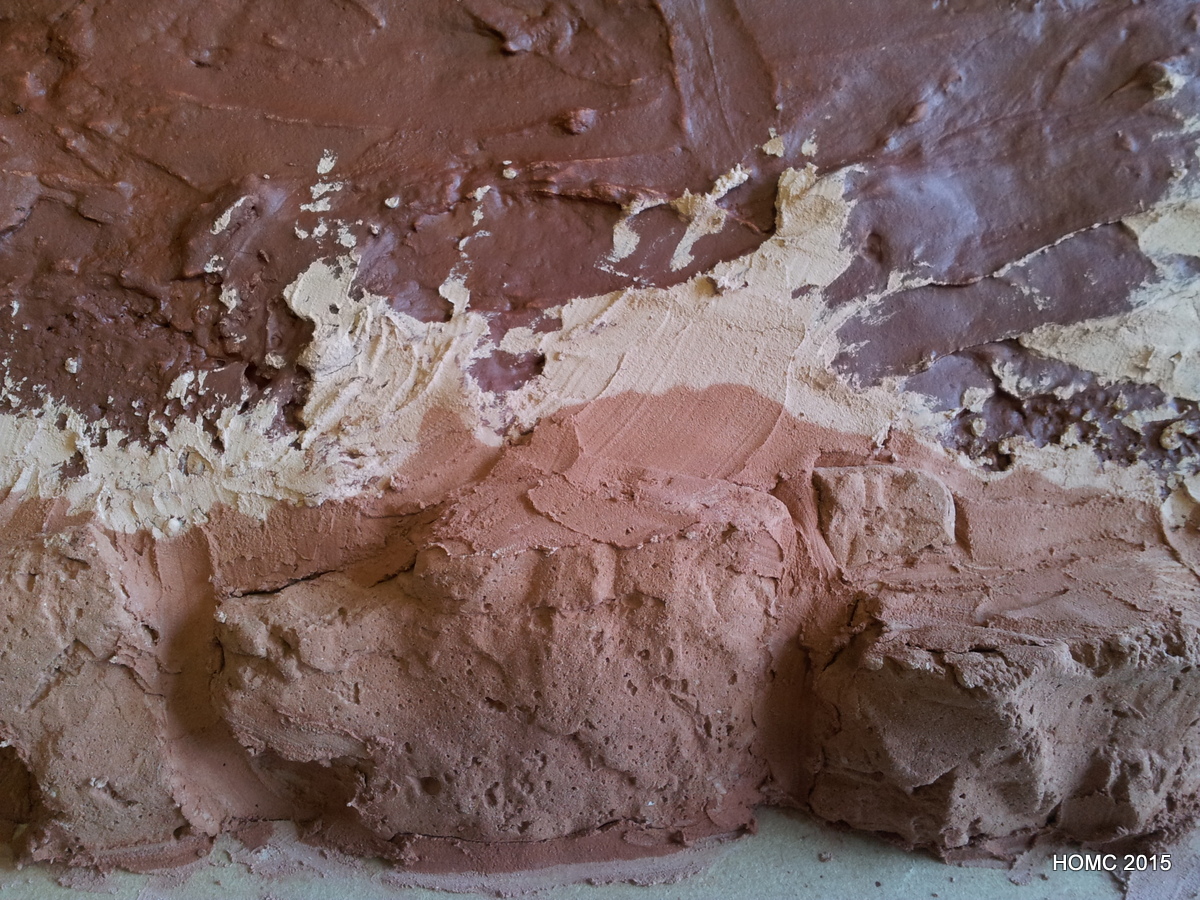
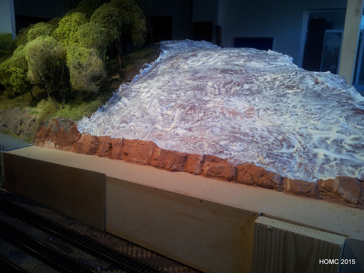
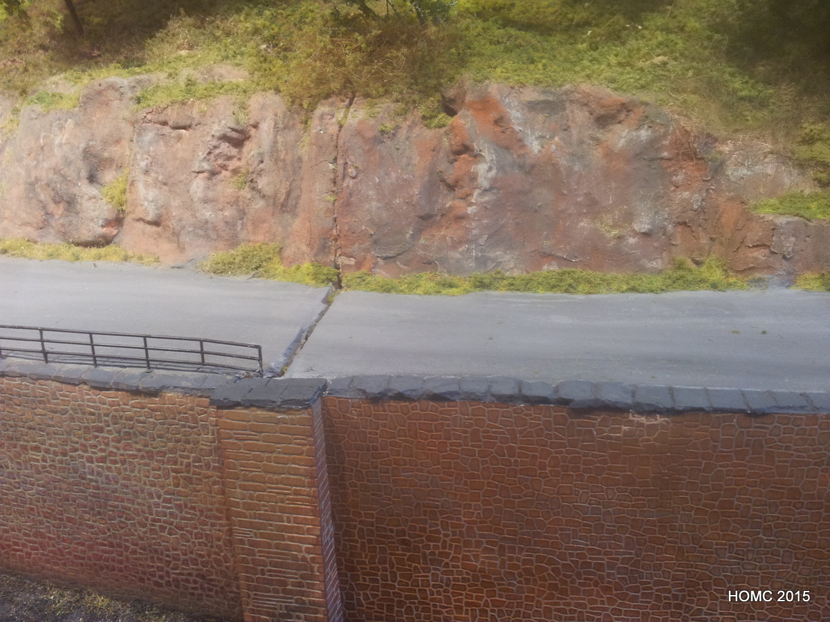
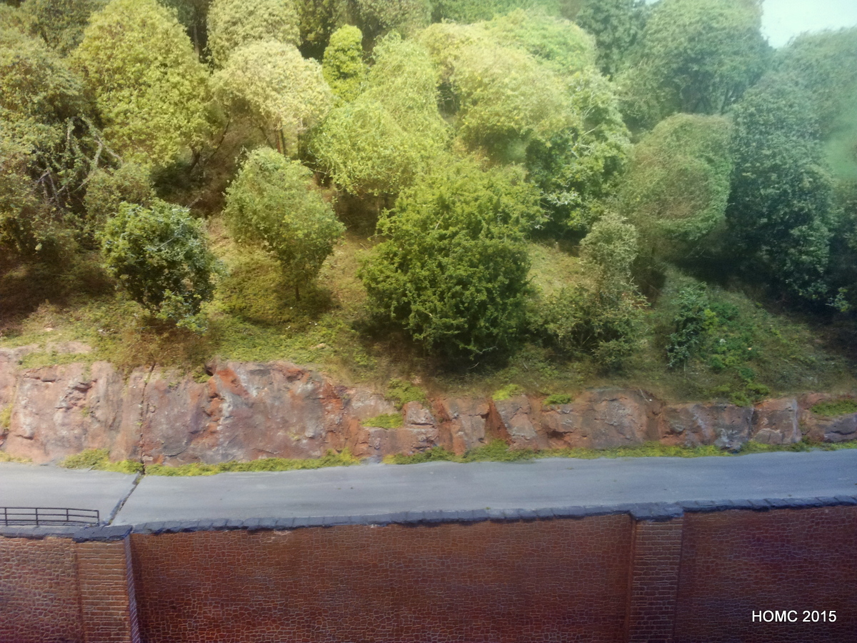
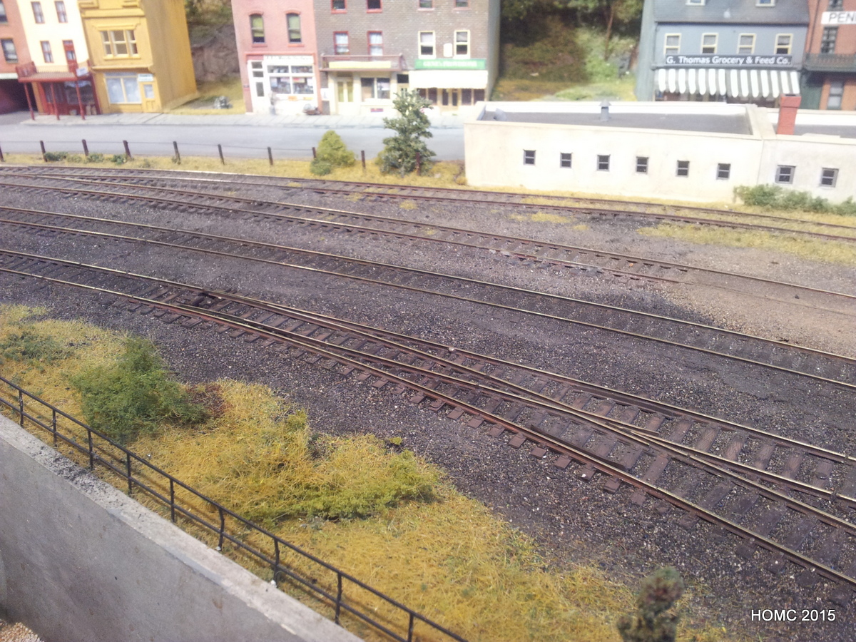
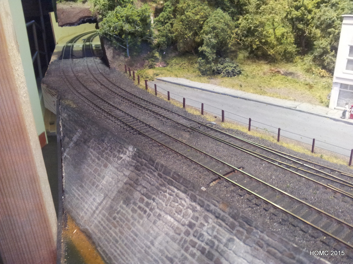
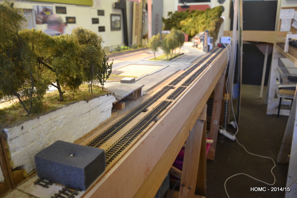
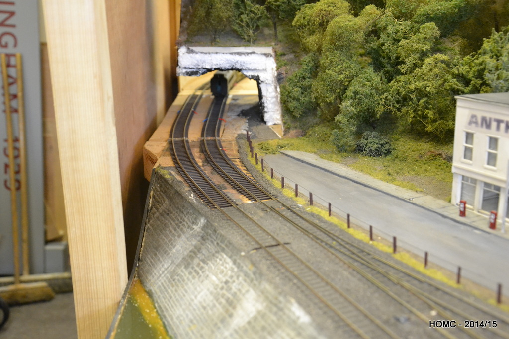
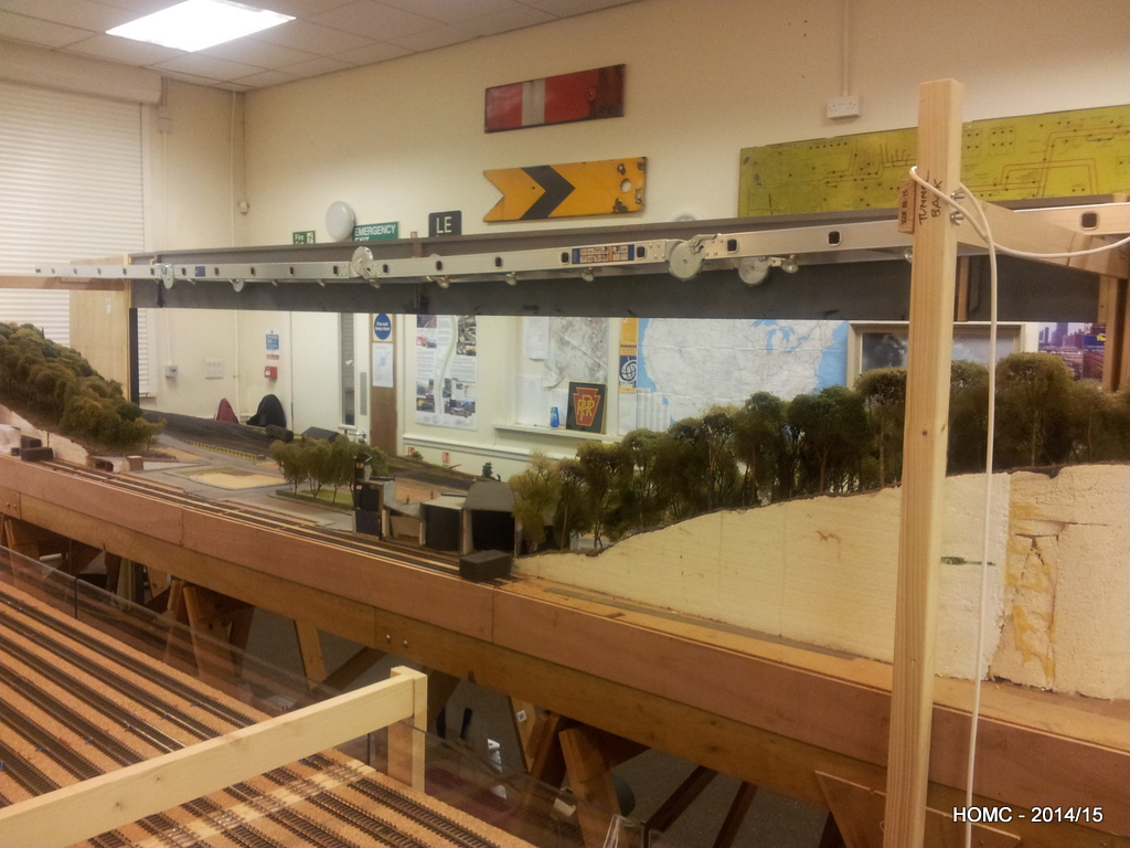
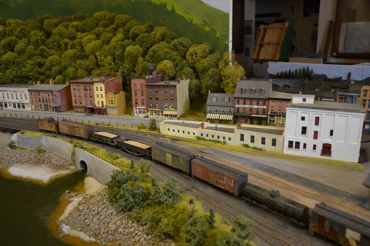
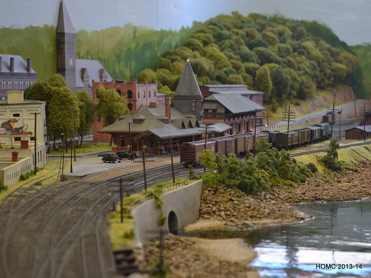
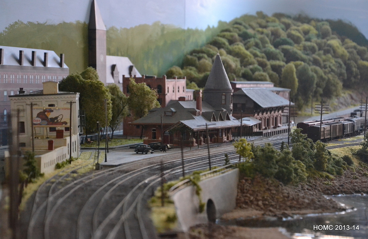
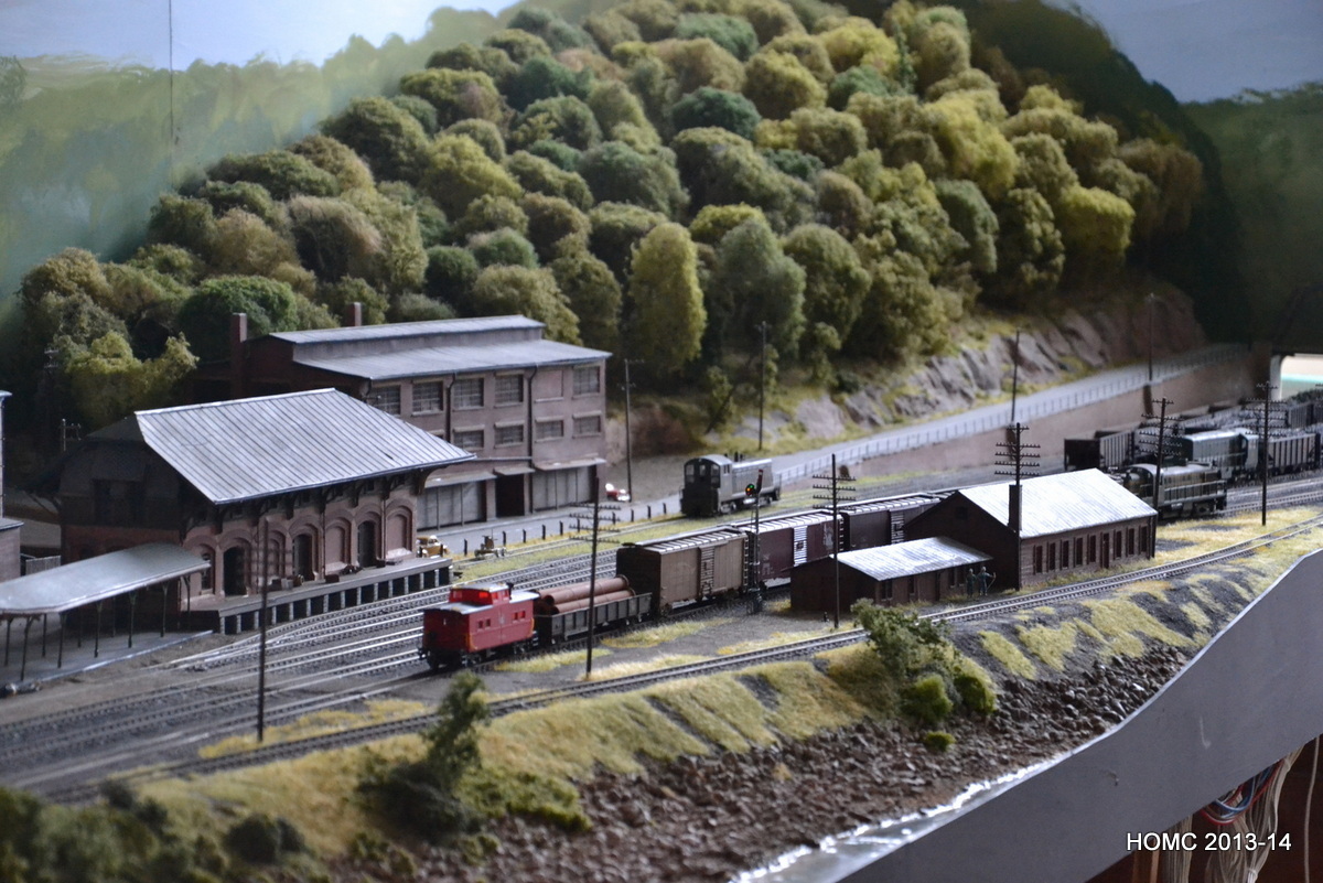
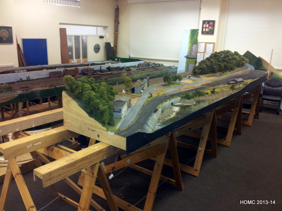
The tidying up from the extension has seen us add scenic material to the right hand end where the layout has effectively now got a 2ft 6inch extension. This has meant carving out a hillside extension in polystyrene (held together with PVA glue) – a very messy job! We then covered this in plaster (pre-colored) and added the roadway with thin medium density fibreboard. Next the rockface was built from rock moulds and these were bedded in with a little judicious carving.
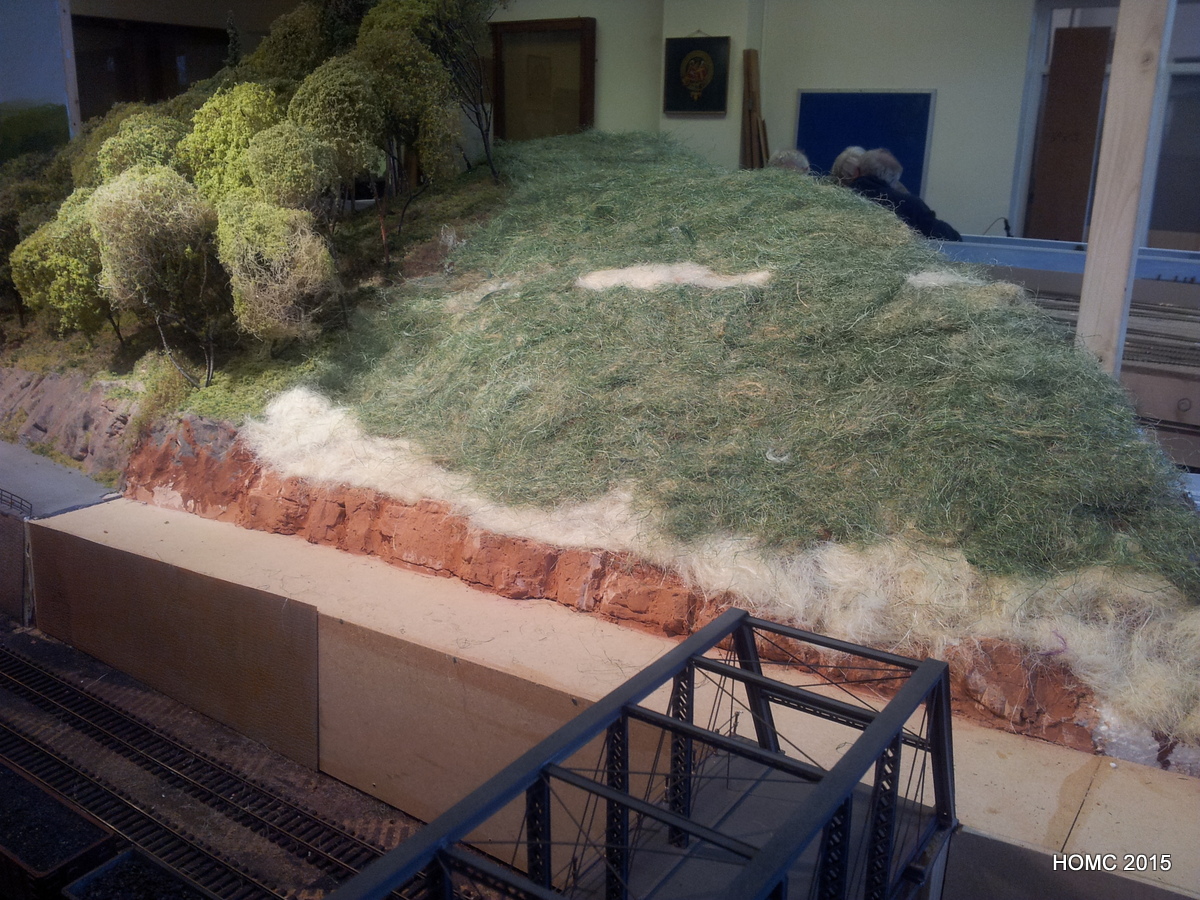
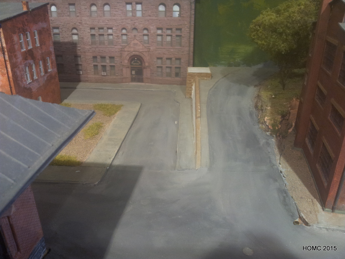
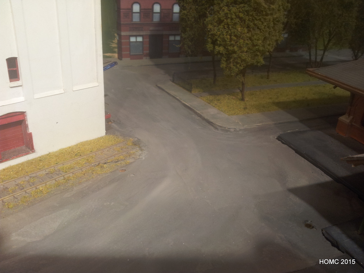
A grass material (from hanging baskets on this occasion) was attached onto PVA. The roadway was extended with colored ‘Artex filler’ material and the grass material was thinned with a beard trimmer (!) before being painted with thinned water based paint. Trees were added as previously described. The wall was extended using pre-moulded platicard and colored mainly with water based pencils to match.
The colored artex filler was used to touch up the gaps in the roadway that could now be filled since the front and back boards had been permanently attached. Artex is an amazing material and, once rewetted, blends in well with new material. Any imperfections can be corrected with a little thinned paint and, once dry, some sandpaper.
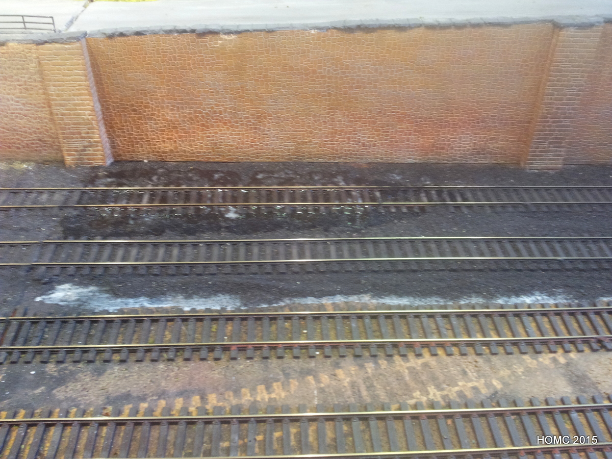
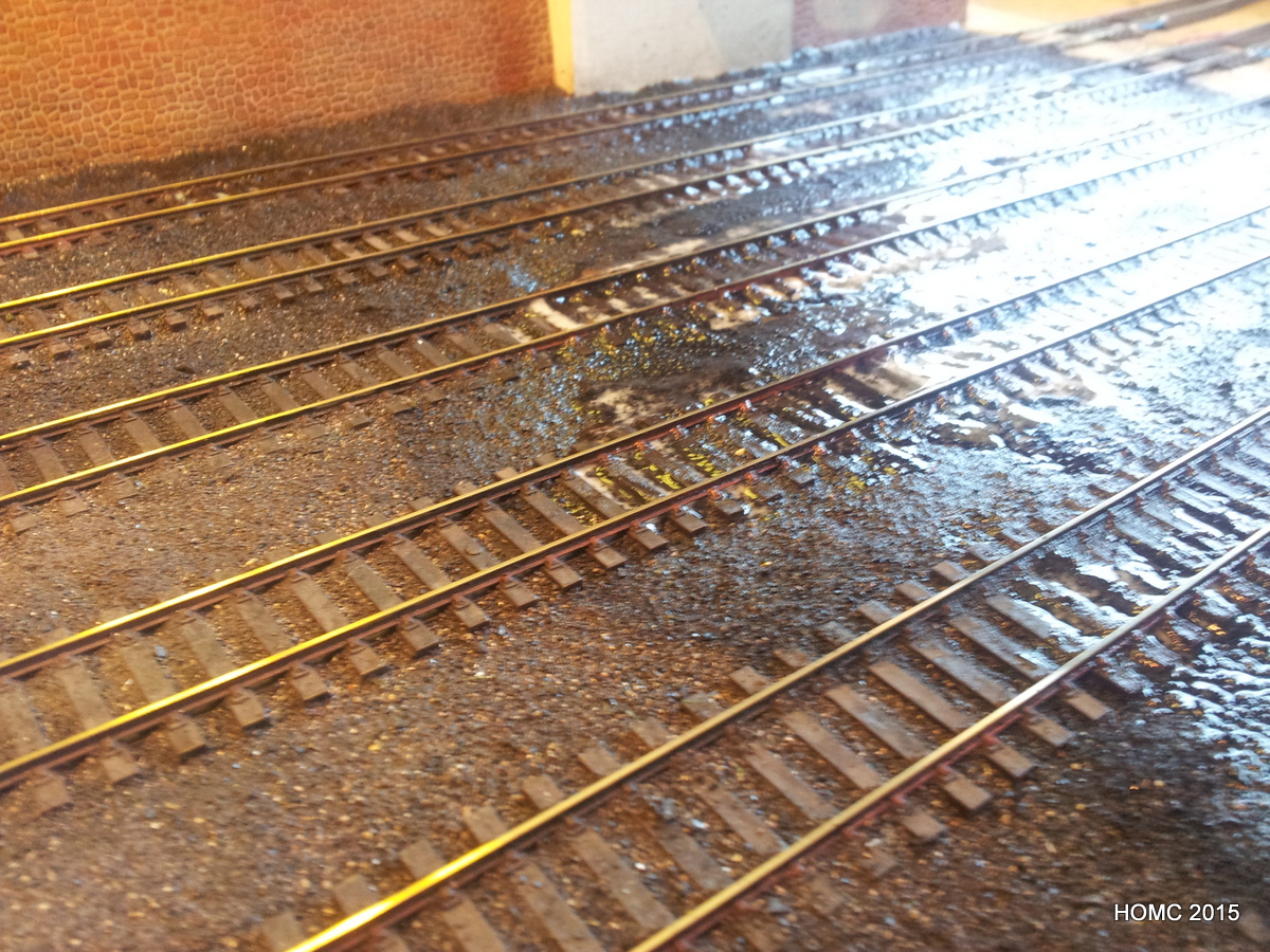
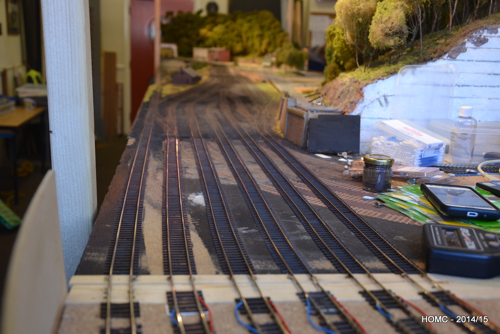
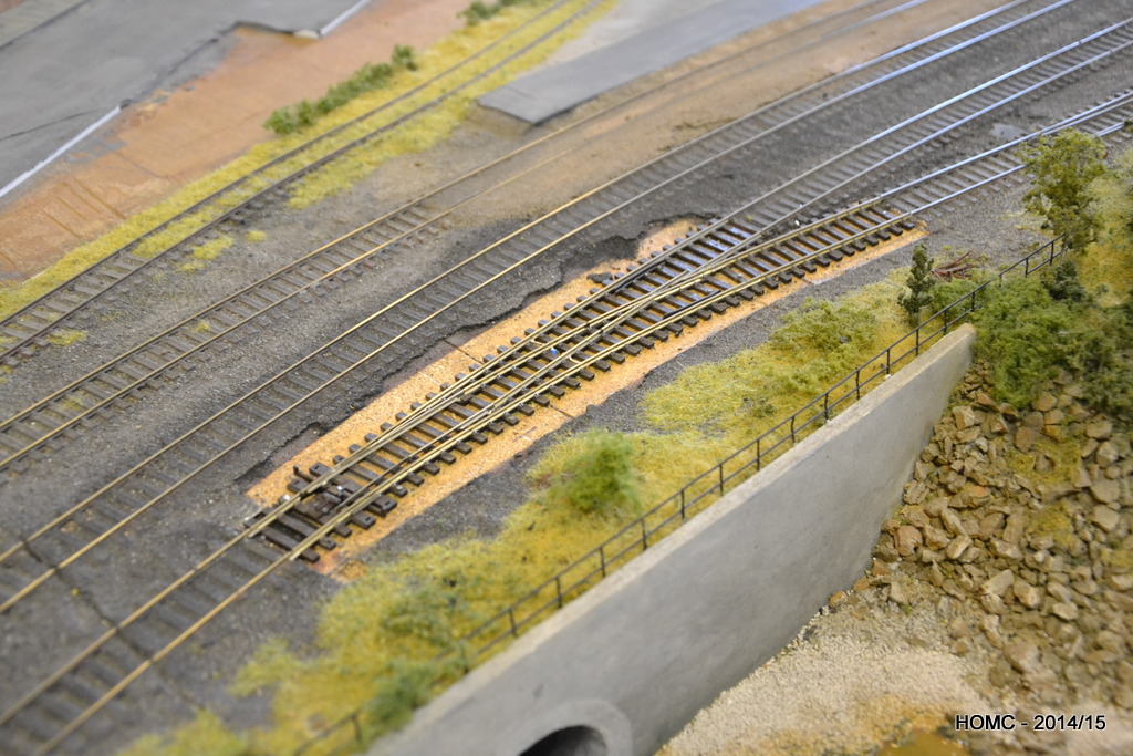
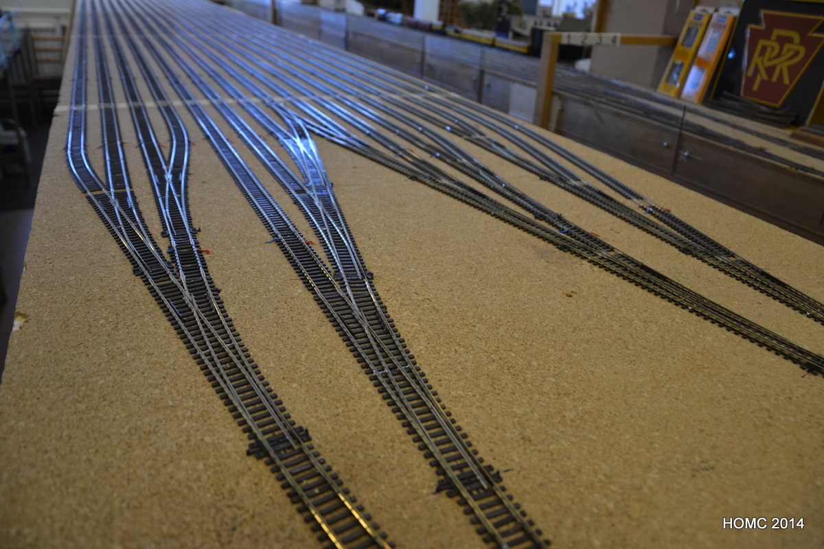
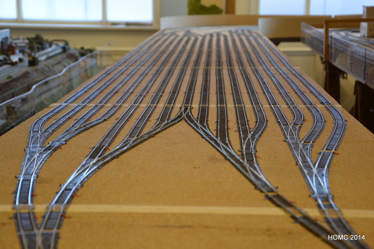
The trackwork was again ballasted with a mixture of coal dust and ash. the ballast was sprinkled onto a bed of PVA – painted between the tracks – and isopropanol (IPA) was then sprayed on to thoroughly wet it. Finally dilute PVA was added with a dropper to wet the ballast in between the ties and further IPA was sprayed on to spread it throughout. Once dry this has a matt finish with no trace of the shininess sometimes seen where PVA is used. The two LH photos below show this process in progress and the two RH photos where is has also been applied at the LH end of the layout and with the replaced switch.
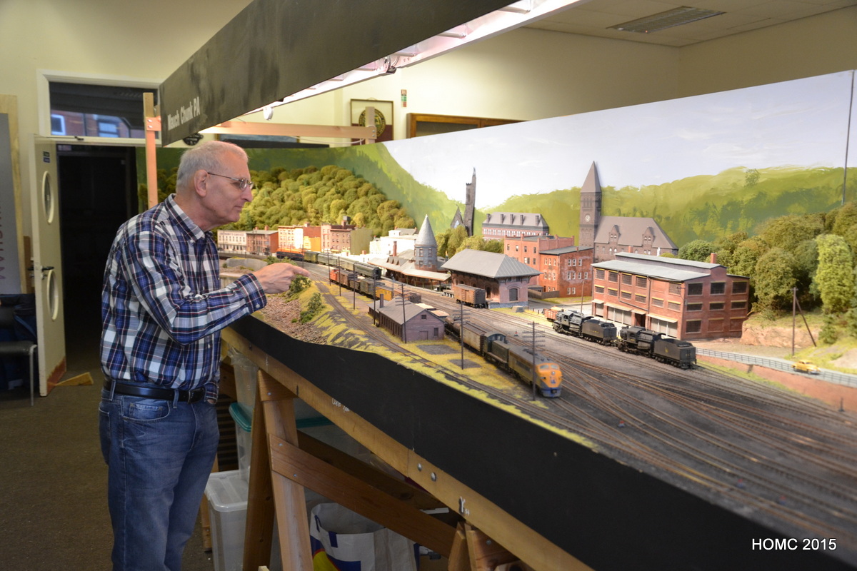
While this was all going on, we had a visit from Joe Kacirek of New Jersey. To our embarrasment the layout ran very poorly but this prompted us to a better understanding of the electrics and a resolution to fix the problems. Joe was very understanding! Some photos from Joe’s visit show the stock out.
As a result of this, we have been involved in a continuous fixing of all the little electrical niggles, changing and repositioning switch motors, modifying software and changing cable connectors.


March 2015
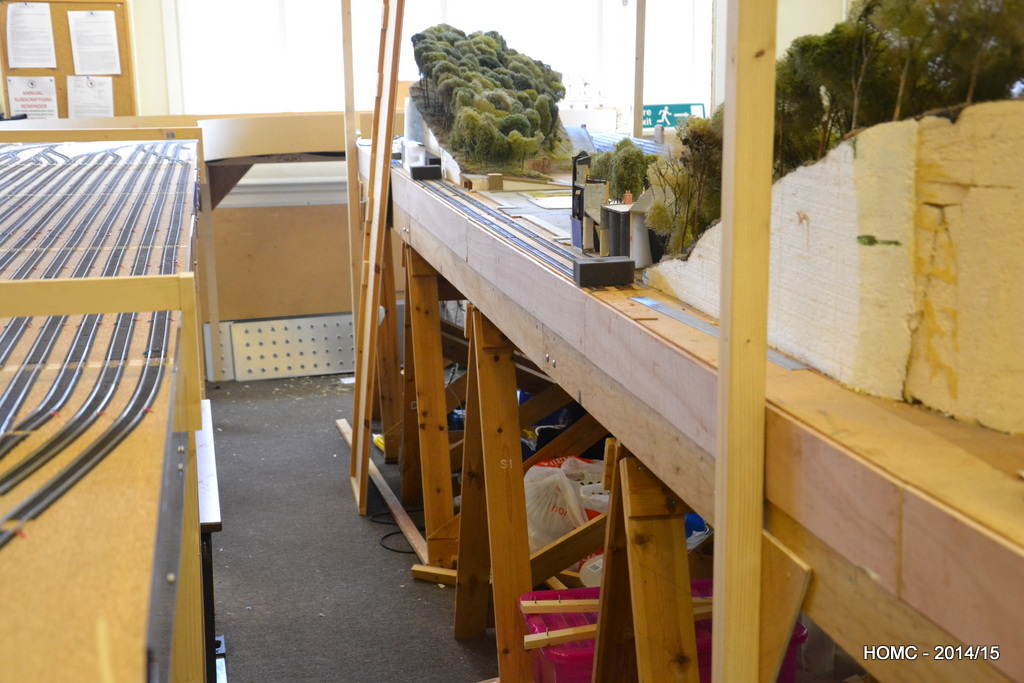
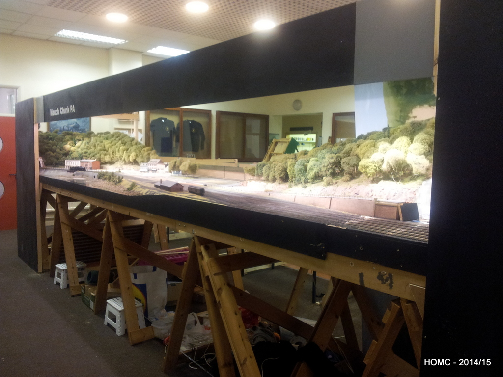
We’ve carried on working hard since last November and have pretty much completed all the baseboard work now. It’s not shown in any detail, but we cut the old staging yard off the back of the main baseboards, leaving just two tracks, which are for testing and programming – one will be DC. A 1ft strip was also removed from the left hand (tunnel) end to give a total modelled board length of 20ft to match the staging yard.
The cutting was done with a rotary saw and finished with a hand saw. The edges were then faced with fresh plywood, suitable braced, glued and screwed. To finish this part of the reconstruction the remnant rear main boards (now about 4ft x 1ft6in) were permanently attached to the front main boards (the original 4ft x 2ft6in) using PVA glue and screws through the bracing points. This means that we have four boards 4ft square and two narrow end boards – one 4ft x 1ft6in and one 4ft x 2ft6in – slightly awkward but – hey!
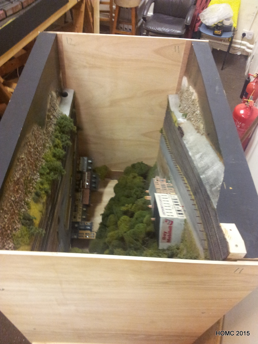
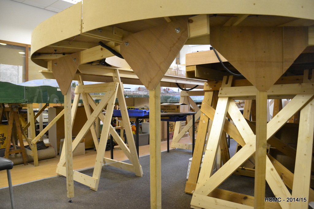
The photos show the new centre well that this configuration gives us – big enough for even the larger of us (I won’t say who that is!) to move comfortably along, although we can’t easily pass except in the ends.
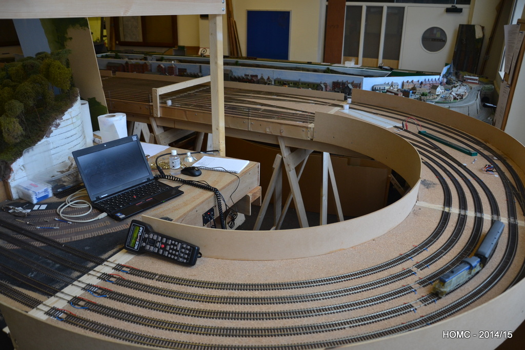
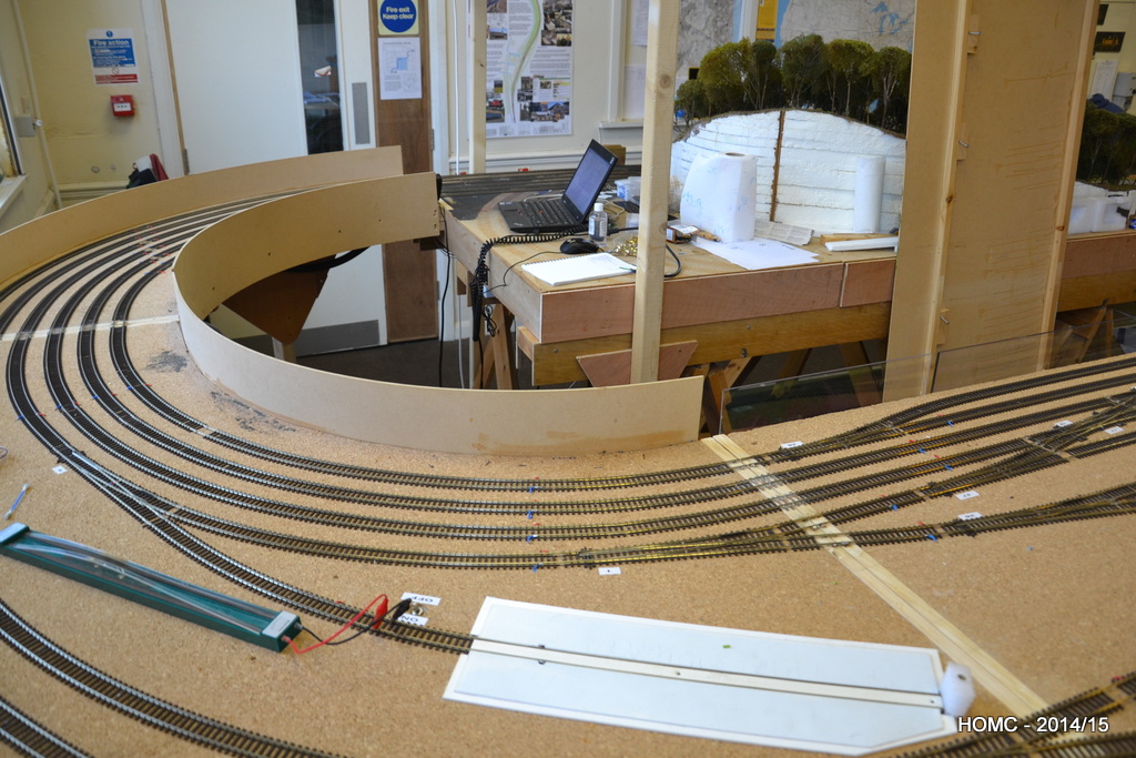
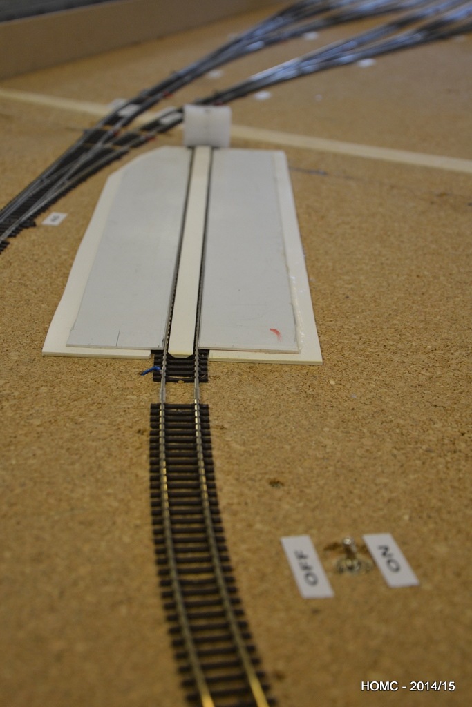
New legs were constructed for the end curves. Also shown above and below is a (re-) railing track which is switched to avoid shorts. Connecting the boards up in the final configuration meant that we could finally lay the connecting track at both ends – shown below.
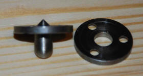
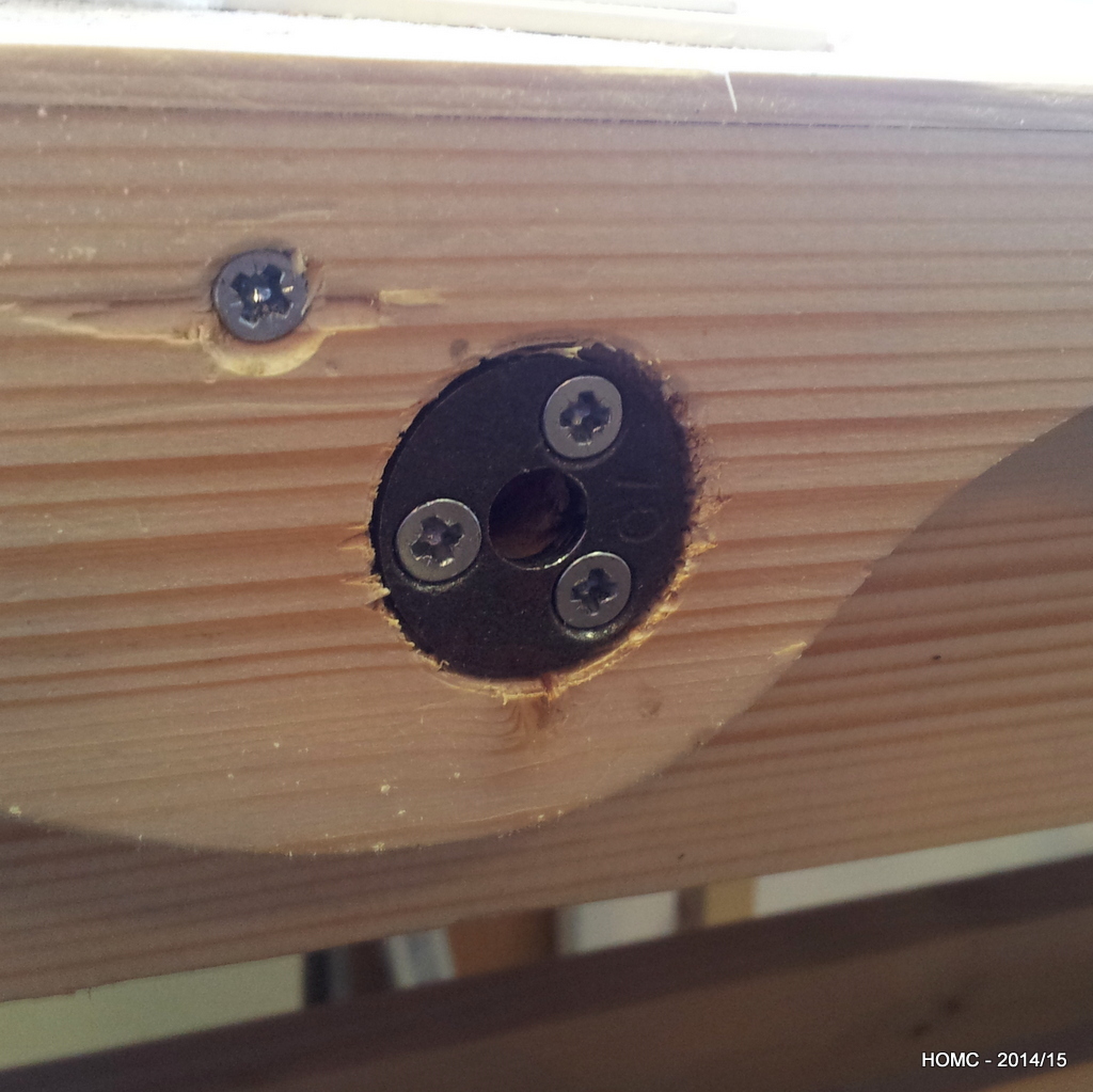
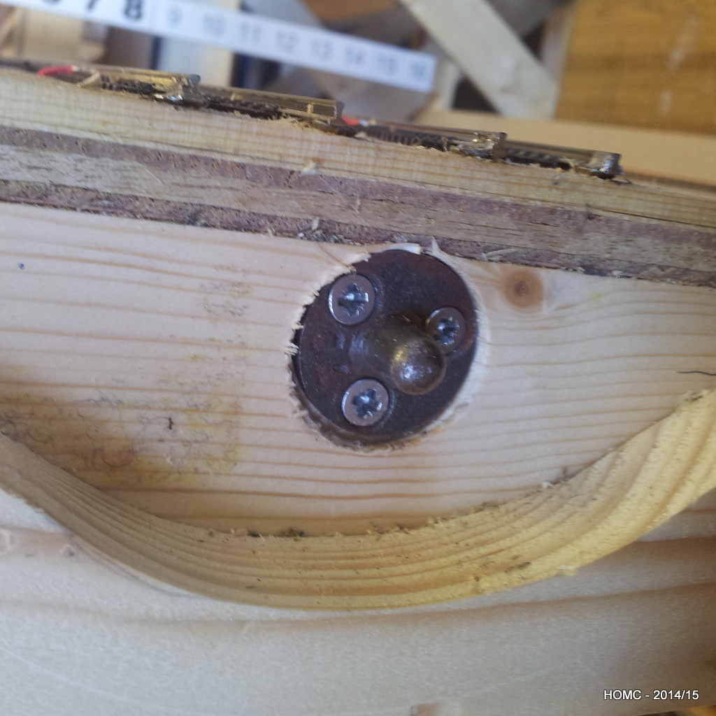
A brief diversion here into the techniques used to ensure that where the track crosses a baseboard join, the stock doesn’t derail. Portable baseboards are the norm in the UK and so this is a major problem. Critical to ensuring that track stays aligned is ensuring that baseboards align in the same position each time they are reattached. The best way to do this is to use board alignment dowels. The best ones have a point in the back of one side that lets you align the two sides for drilling. The second and third photos show these in our board (after the curvy edge system had failed to align the boards well enough!).


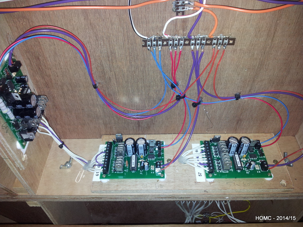
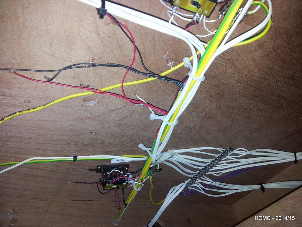
The wiring on the front had been installed many years ago, and so the switch control wiring was disconnected and then rewired to MERG DCC boards to give the same switch control system as in the staging yard. Note that the DCC switch control boards are always attached to a vertical surface to make maintenance easier. One switch on the front (on a curve) was replaces with a commercial Peco switch – which has proved better, but not perfect.
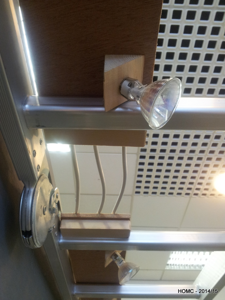
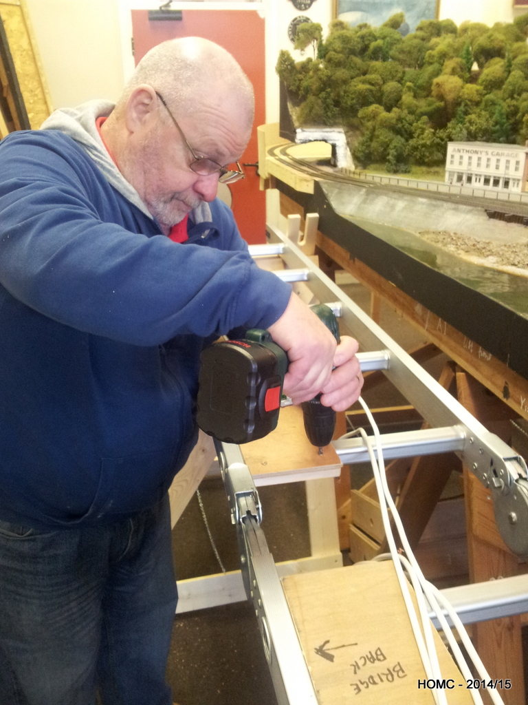
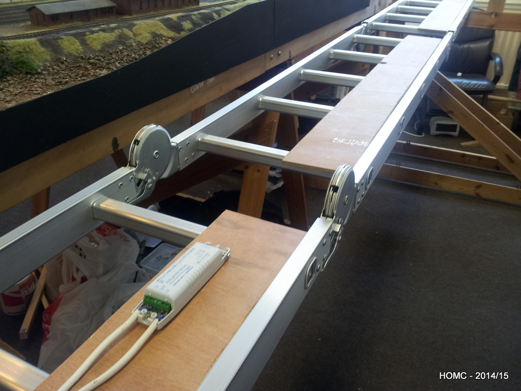
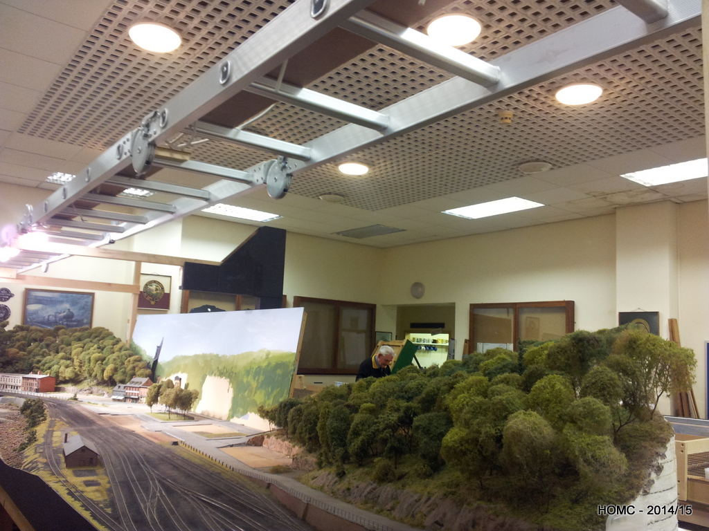
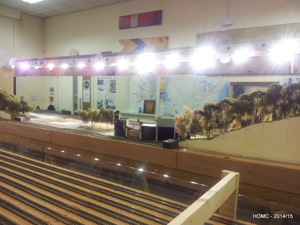
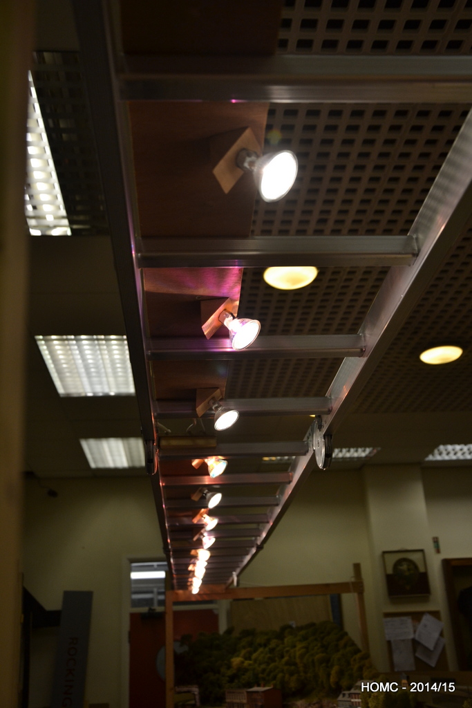
Everything working on the boards, we then moved on to the lighting and the gantry. After seeing a layout at the Mickleover (Derby) club using an aluminium folding ladder to support the lighting, we managed to purchase a 20ft ladder that would work for us. Although it was not completely level when supported at only the ends, it was rigid and so the slight central dip could be accommodated when mounting the fascia boards.
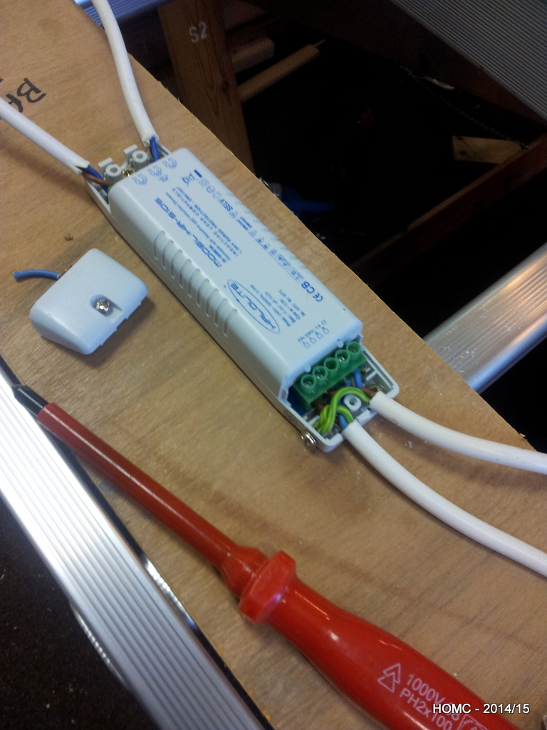
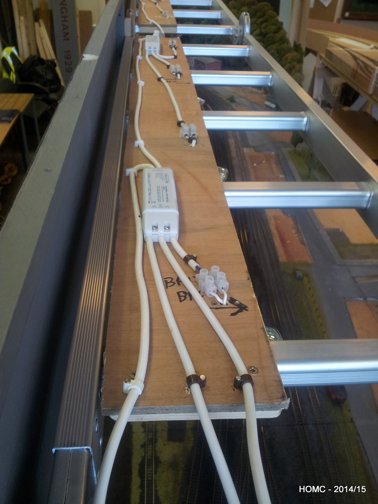
Lights are DC (12v) halogen, wide angle floods of 20, 35 and 50 watts. We attached these to the bottom of strips of plywood at 45 degree angles with basic lampholder bases. Along the top of each board were the transformers and the wiring. The plywood simply rests on top of the ladders and the fascia hangs off the front. A simple H frame at each end supports the ladder.
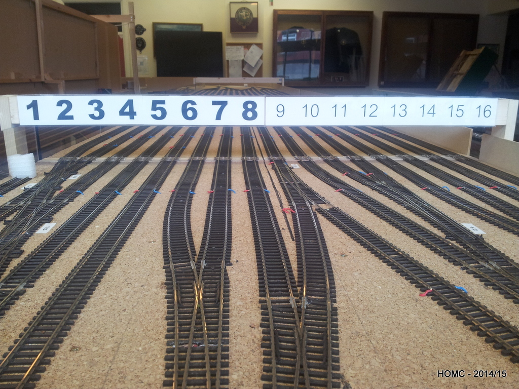
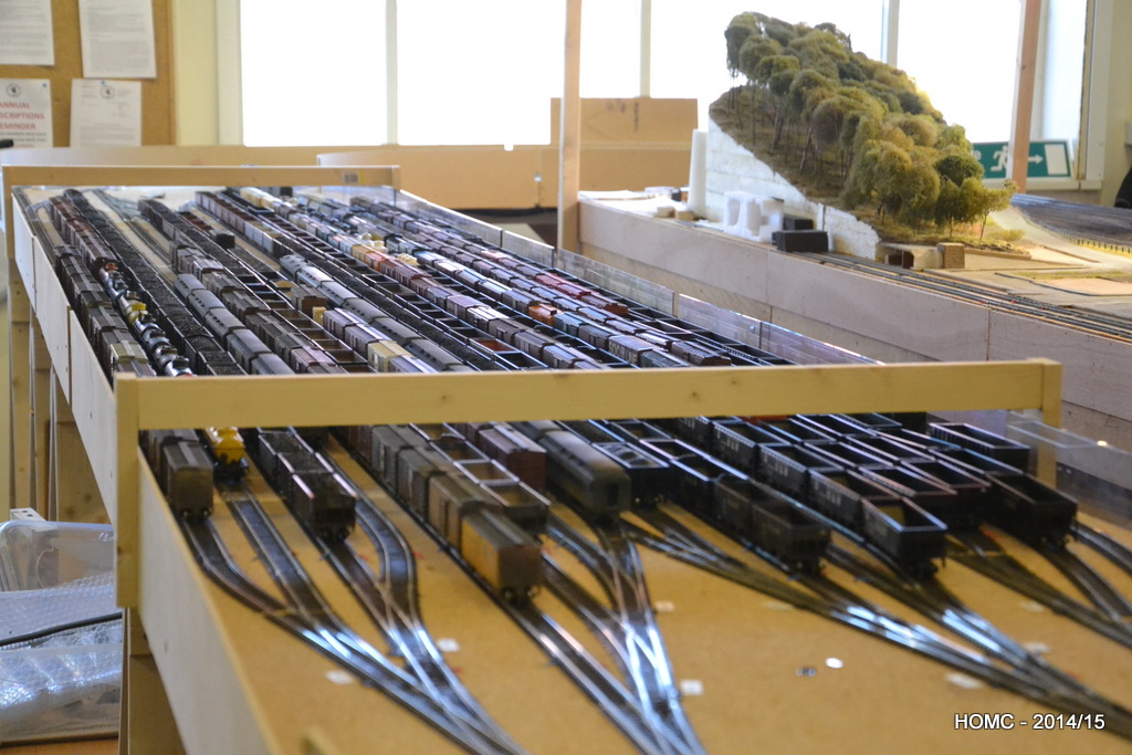
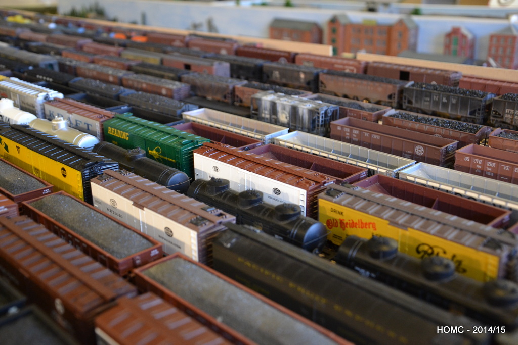
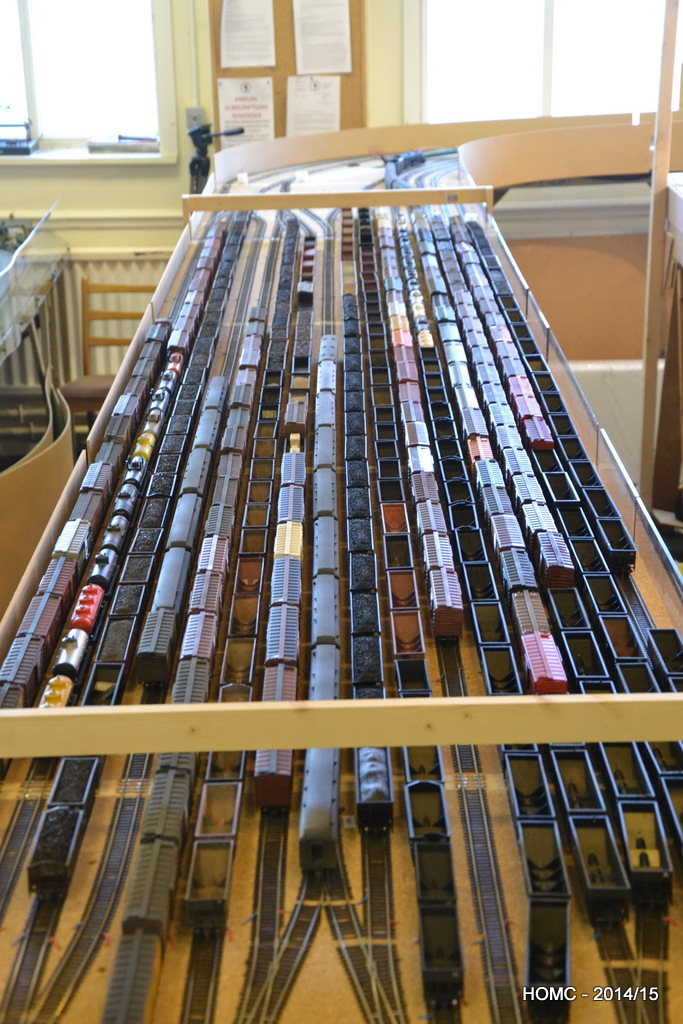
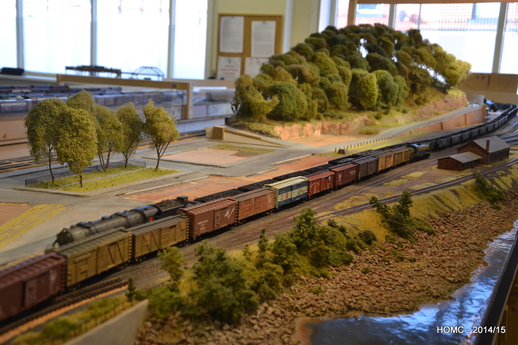
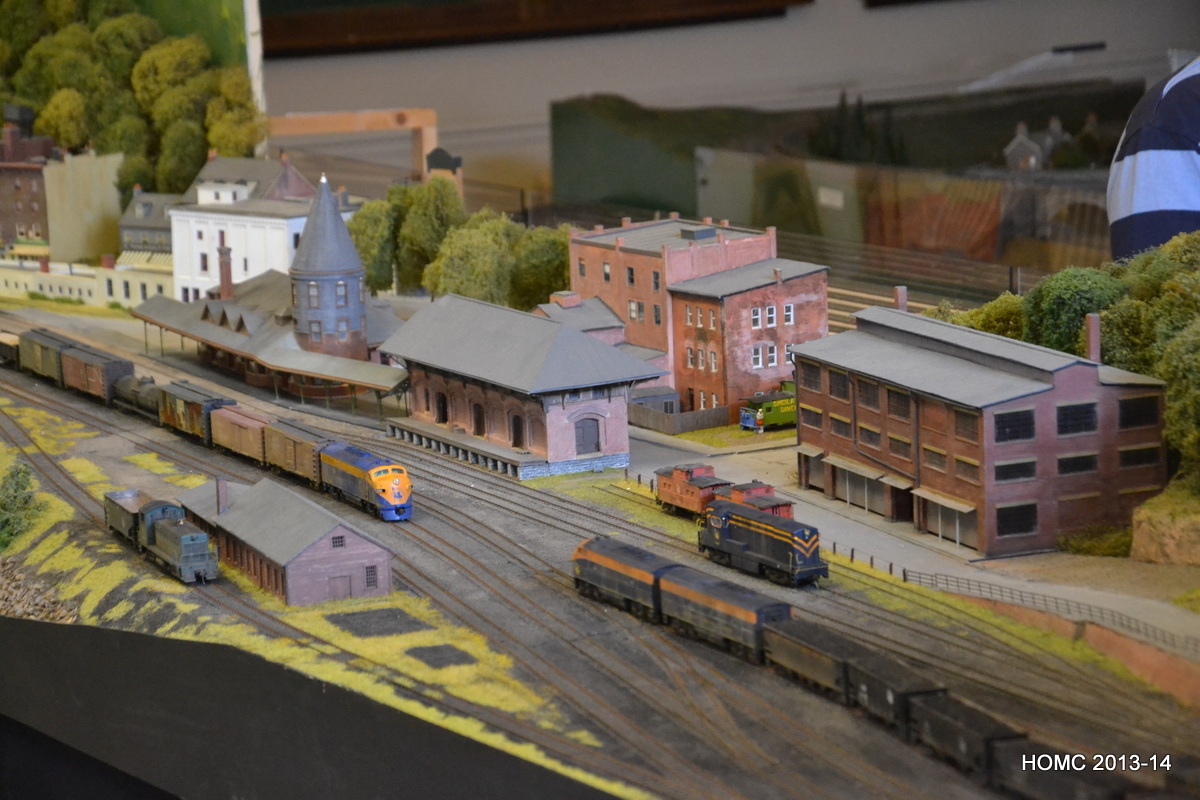
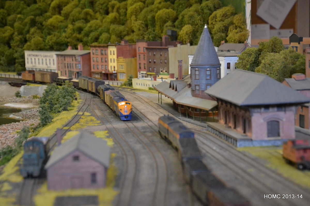
All this work completed, we decided to put our stock out on the staging yard and were quite shocked by how much we had – especially as most of our locos can’t pull such long trains. Still quite a lot of weathering, re-wheeling and Kadee-ing to be done though!
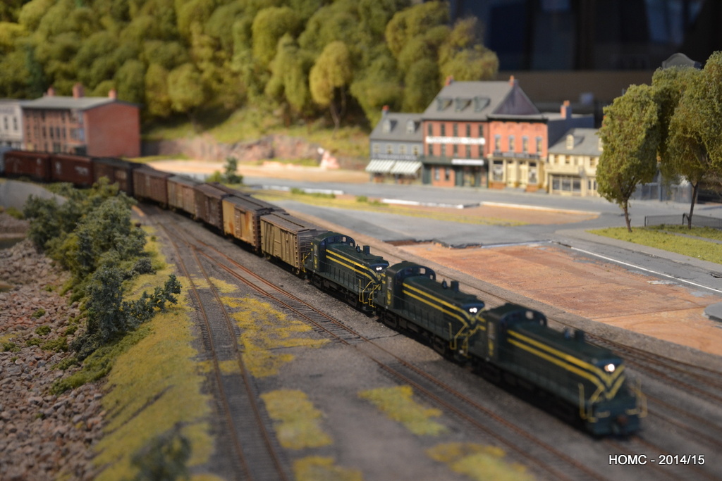
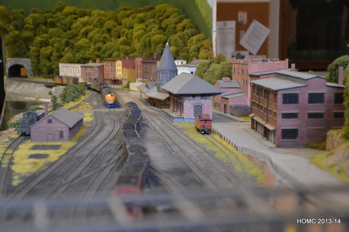
Finally a shot showing a consist of new (as yet undetailed) Athearn RS3s and then one with a N&W articulated interloper with a long empty coal train (note that the buildings have been removed for safe keeping). We are now moving on to add more hillside and roadway at the RH end, and then will work along adding detail to the scenery.
November 2014
Despite my hopes that the updates to the site would become more regular after Gordon’s retirement in April and my continued life of leisure, what has actually happened is that we modelled at a high rate instead. As Doug is working a four day week, we modelled on Friday mornings as well and this made a big difference.
We had a good summer and used this to carry out repairs on our clubhouse – including demolishing a 120ft portacabin which also kept us pretty busy!
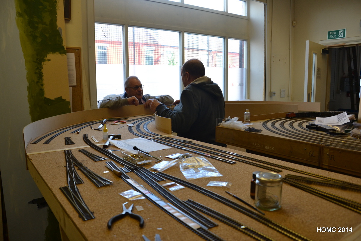
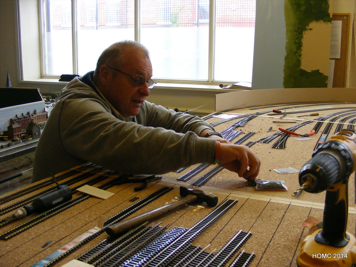
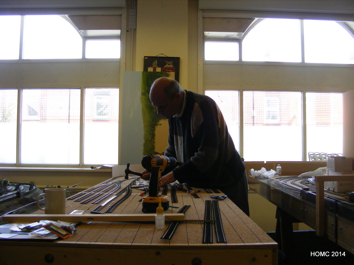
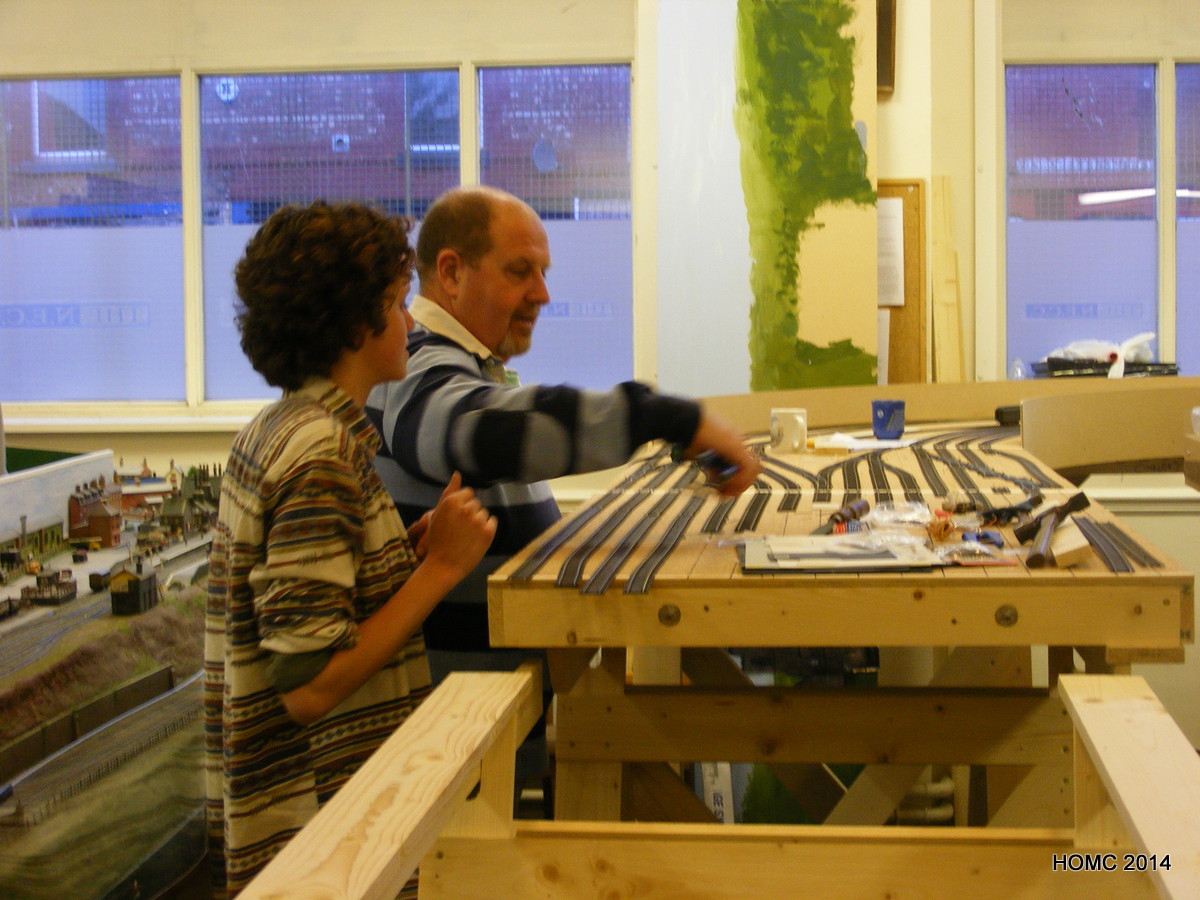
Here we are starting to lay track in the staging yard – if all else fails, hit it with a hammer! Even my daughter came in to lend a hand on a visit back from her midwifery course. The track laying progressed well. By August it had pretty much all been laid.
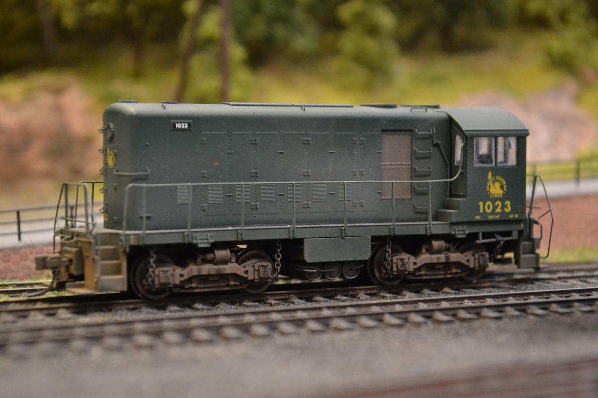
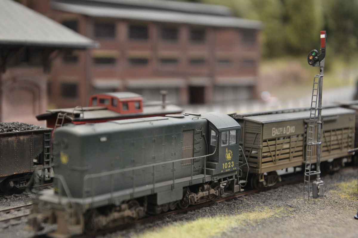
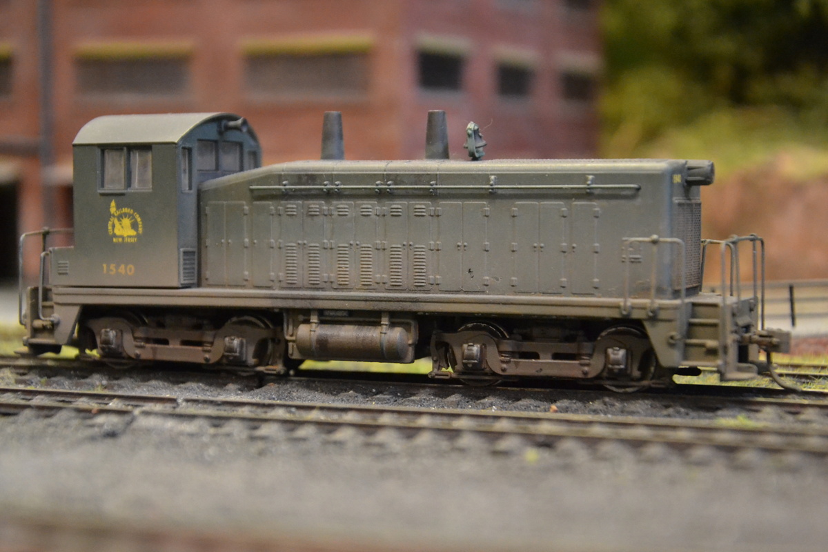
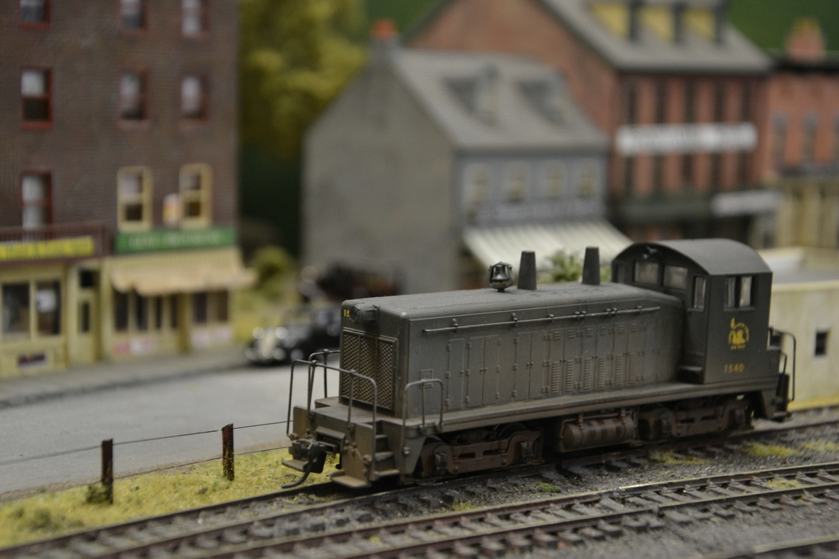
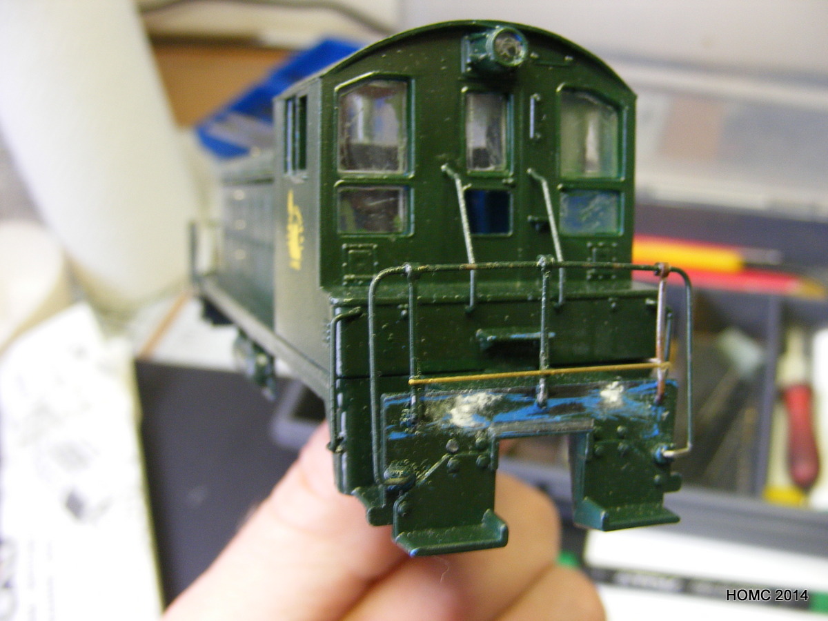
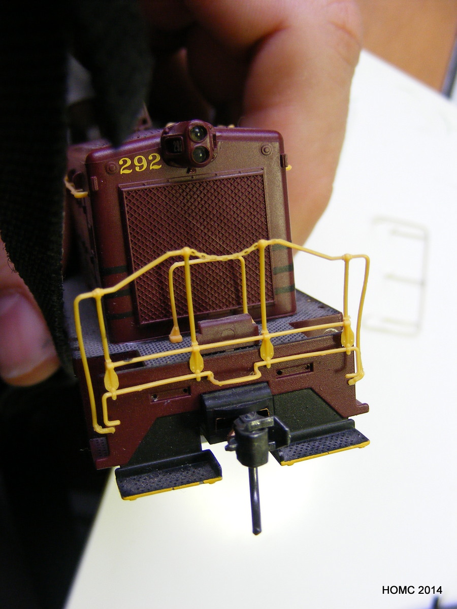
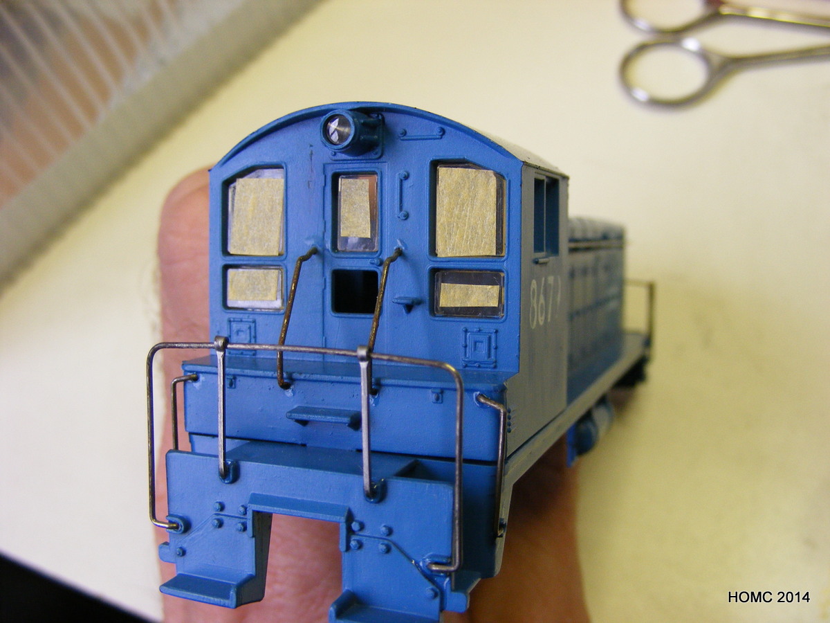
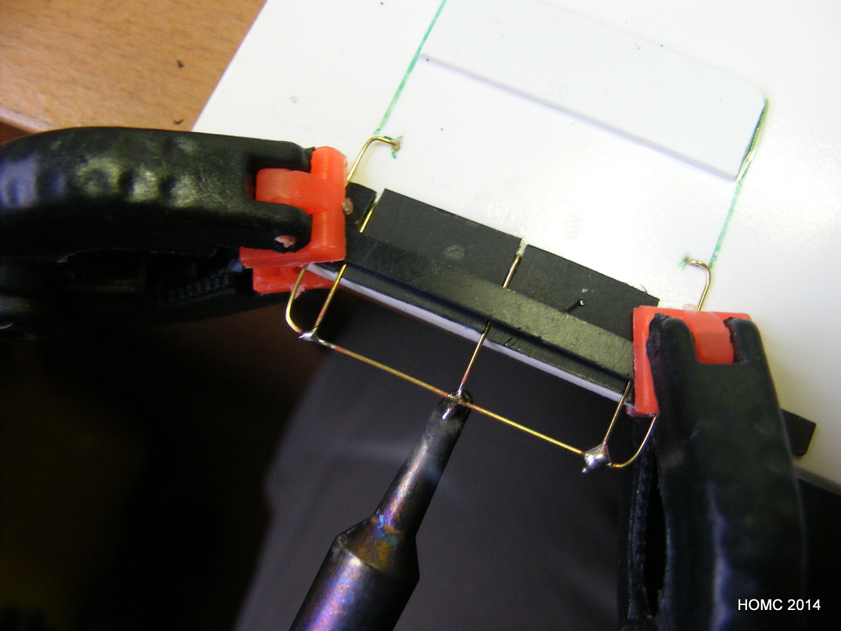
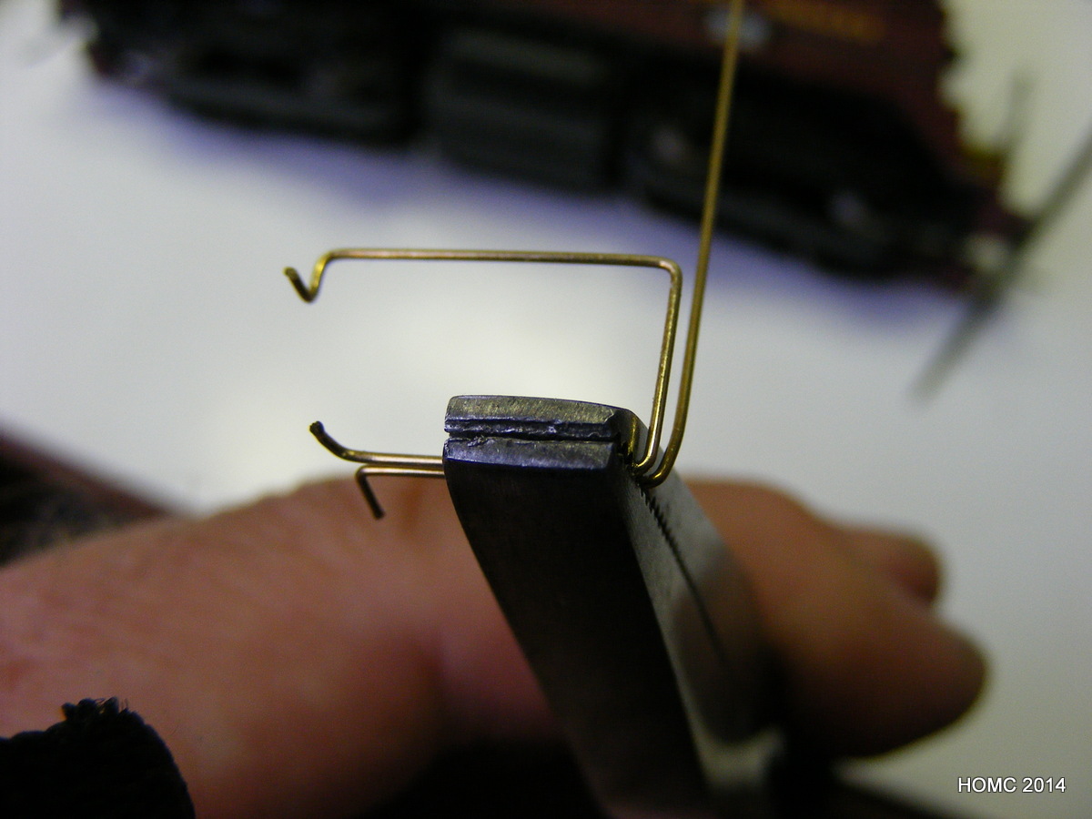
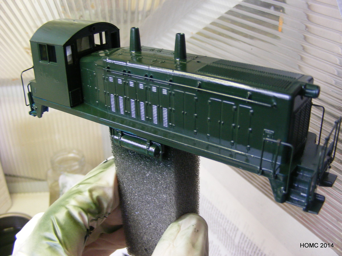
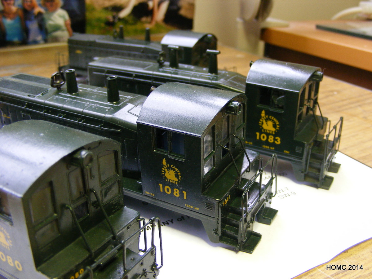
In the meanwhile, Steve was working on customising some SW7s and SW9s for the CNJ. Athearn and Proto-2000 stock was used as the starting point. Both jigs and hand bending were used to prepare the CNJ-style handrails – some were soldered, but most were superglued.
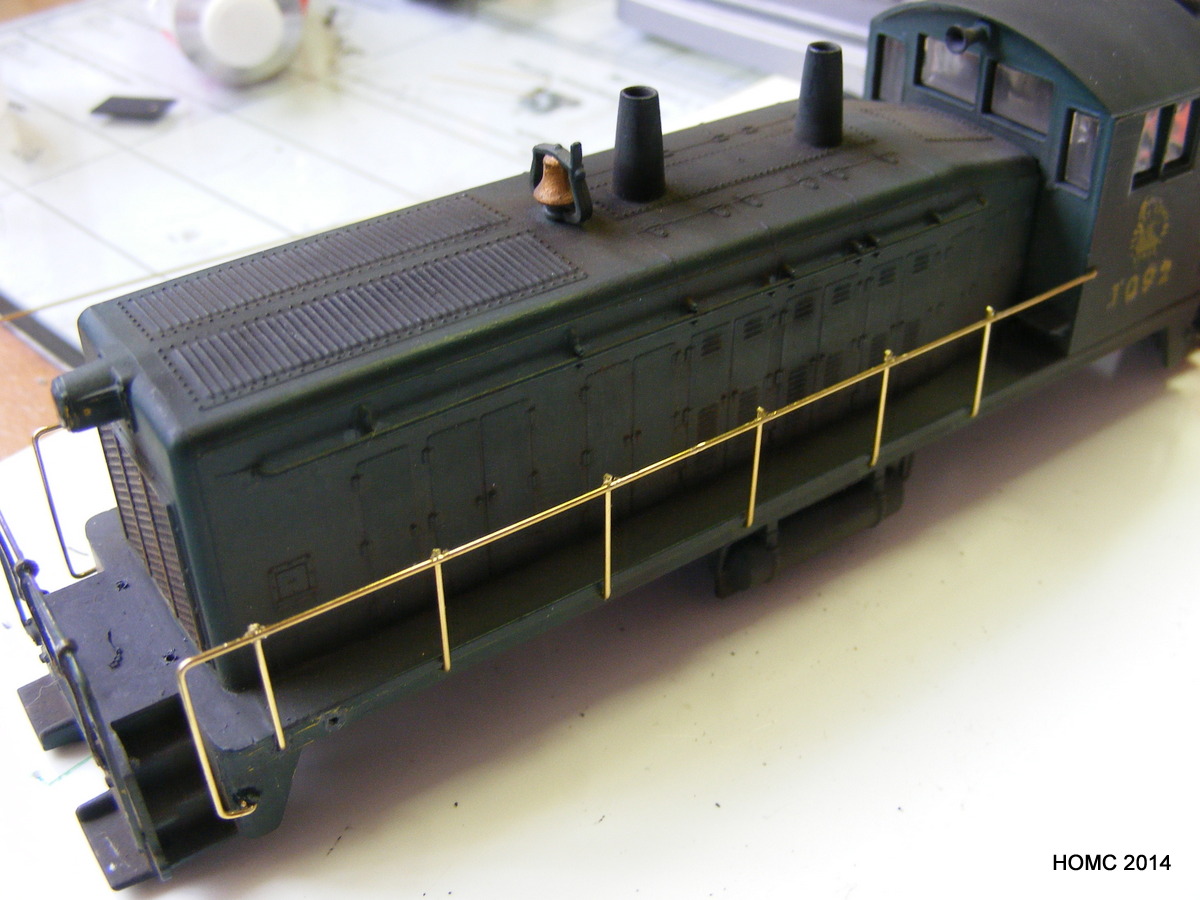
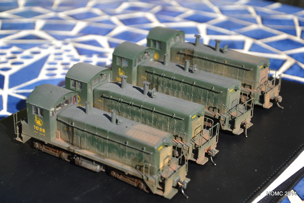
Handrails were added to different styles depending on the prototype, as were minor variation in the vent stacks. Once handrails (and some grab irons) were complete, the bodies were airbrushed with my own mixture of gloss green. RBH water slide decals were then applied carefully and the models were then sprayed with matt cote. Finally all were weathered with a mixture of techniques. Three were chipped and one set up as a dummy as not all the motors were usable.


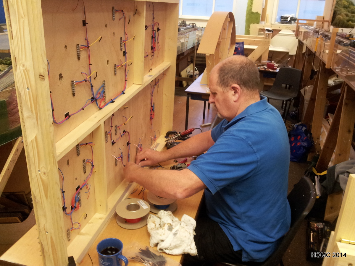
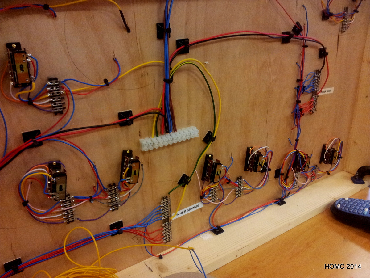
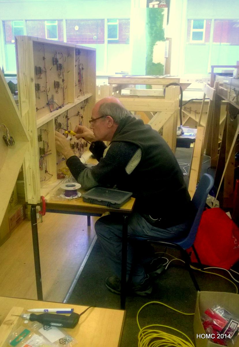
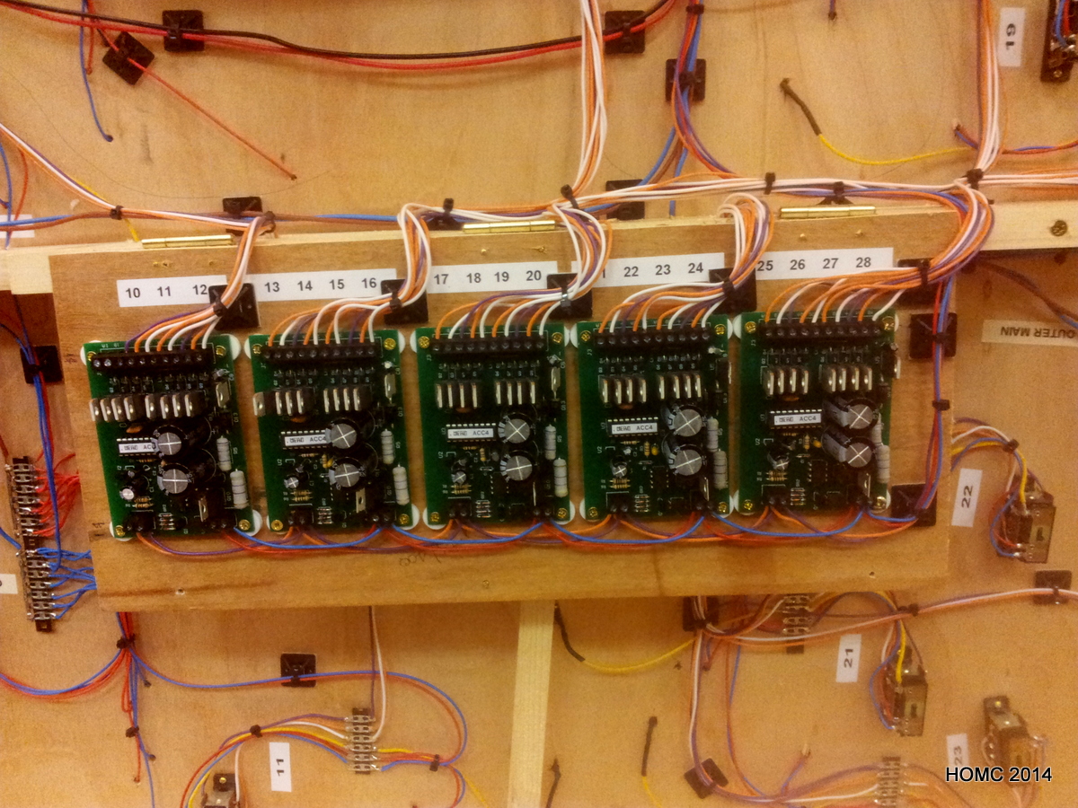
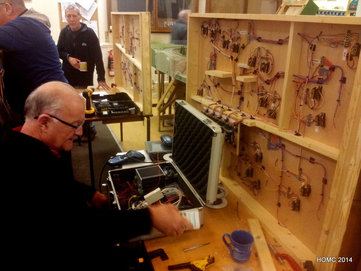
Meanwhile, back at the club, the hard work of wiring up the track and switches was proceeding – led by Doug, but with all three of us taking a share. Later, Doug withdrew from this exciting activity due to pressures of work and other interests, but we continued to fit and wire switch motors (Peco) with the help of Bill, and MERG DCC switch controller boards. These latter were mostly built by our club specialist (Derek) and wired in by Steve. Derek then configured them for us.
We set up computer control with the Big Bear software package – which works well. The track panel component (left) can be downloaded for free.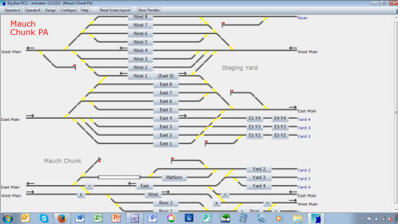
..and all the time the trains kept running round! We are now cutting and reconfiguring the old baseboards, removing the old staging yard, and hope to have finished this stage before Christmas.
April 2014
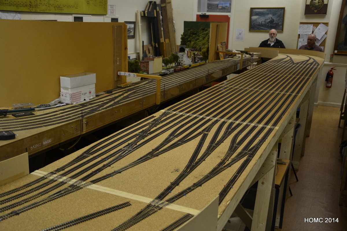
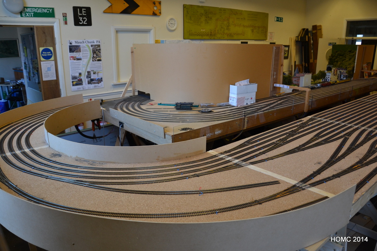
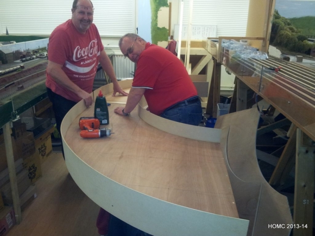
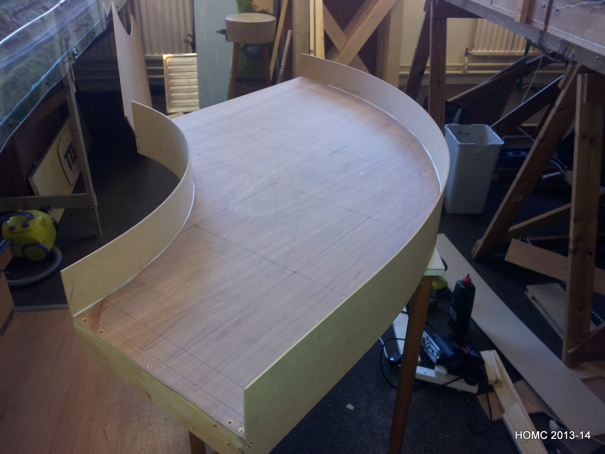
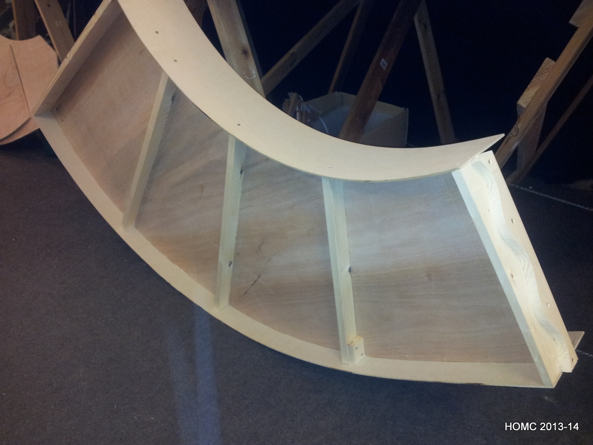
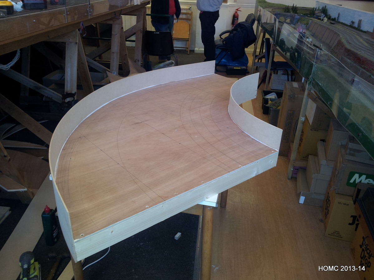
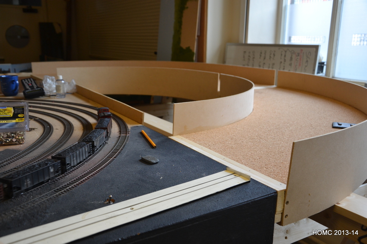
Although the five 4ft by 33 inch staging yard boards were already constructed, we still had to make the curved end boards. The photos show their construction. We again used a ply base and softwood bracing, but the sides were from 4mm MDF board which bend nicely. All held together with screws and white glue (PVA).
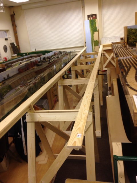
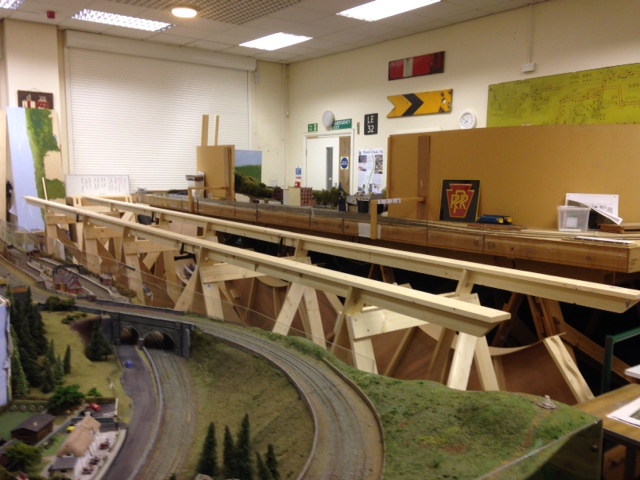
Doug came up with a support system reminiscent of that used on the scenic board, but this time using a softwood T-section. This fits into slots on the top of the trestles. and is very strong. The last two shots show the end boards and the first staging yard boards erected a couple of weeks ago (that’s me being smiley!). Finally a few shots of the stock running while we extend – I’ve been weathering the F3 units and cabooses with Pan Pastels after the article in Model Railroader. Generally we’ve been very impressed.
Paul and Dave are still modelling nearby us in the clubhouse on their EM (4mm scale, 18mm gauge) layout of a local station and we often go for a drink with them after the modelling sessions.
Hopefully the update to the site will become more regular now. Gordon is retiring this Friday (Easter Friday) and I was made redundant last October so am semi-retired at 58. Doug is working a 4-day week so often has Fridays free. All-in-all this should mean more modelling time as we start on track laying and wiring.


2nd half 2013
We left the layout with construction just starting up again in May. Here are Doug and Gordon working on the new staging yard baseboards – plywood top and softwood bracing. I’m helping by taking photographs. We used ‘EM-gauge society’ baseboard locators – metal pin and holes that screw to the ends of baseboards; These are visible in the third picture where we are weighing down the cork with anything to hand. The fourth picture shows an unusually summery set of modellers and below that are some shots of the layout in July.
Also in July, we completed purchase of the clubhouse from our local council and that meant that the plans to move into the main hall, with more room for our extension, became possible.
As some of you will know, we were very sad to lose Chris Bennett at the end of August – he had prostate cancer and had been in hospital and then a nursing home since the spring. His modelling prowess is evident in so many of the structures on our model of Mauch Chunk, as well as in the overall construction. He is sadly missed.
Over the Autumn (= the Fall) we finished the baseboards while one of the other groups modified the new annex building that we had acquired on the site. This would mean they could move there out of the main hall making room for us. After the end-October exhibition, which their layout attended, they duly moved into the annex. We cleared the space left and in January moved Mauch Chunk through into the main hall. We were delighted that even with inexperienced modellers we dismantled it in a couple of hours and then re-erected it (see photos above) in another couple. At the end of this we had stock running! A testament to Chris and Paul’s construction and wiring.


2013 weathering
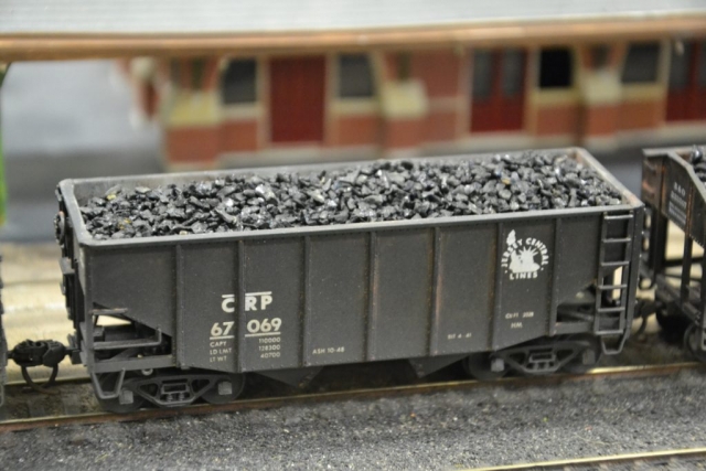
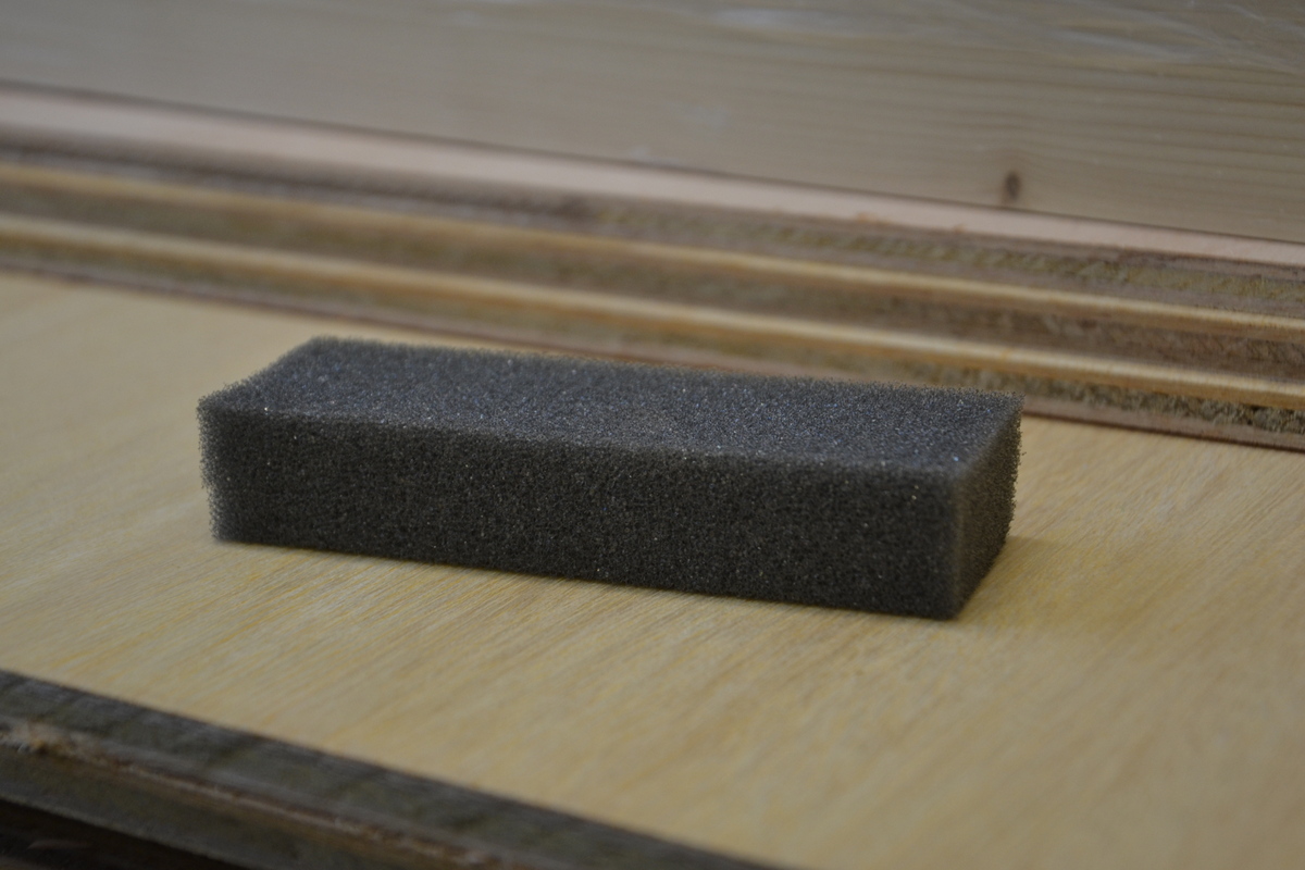
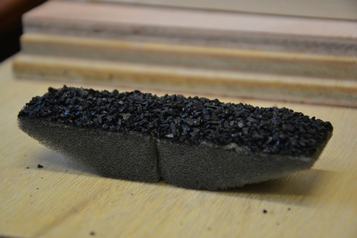
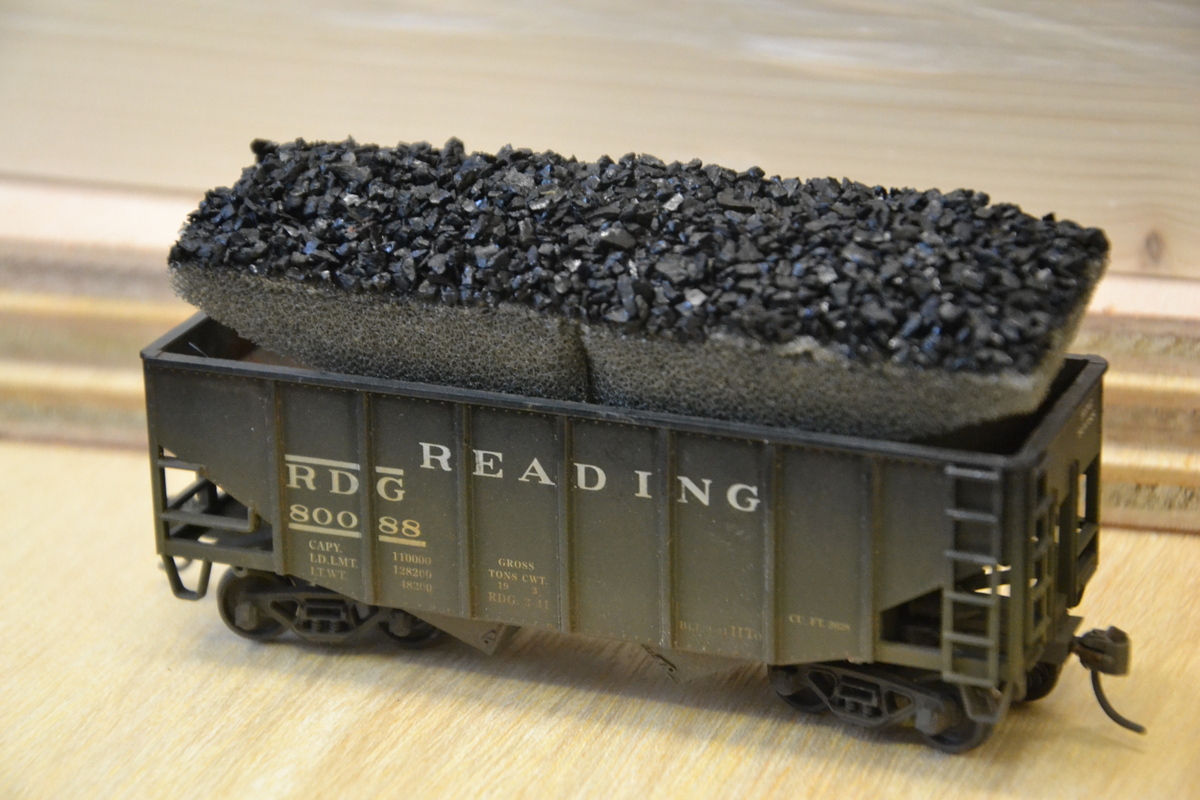
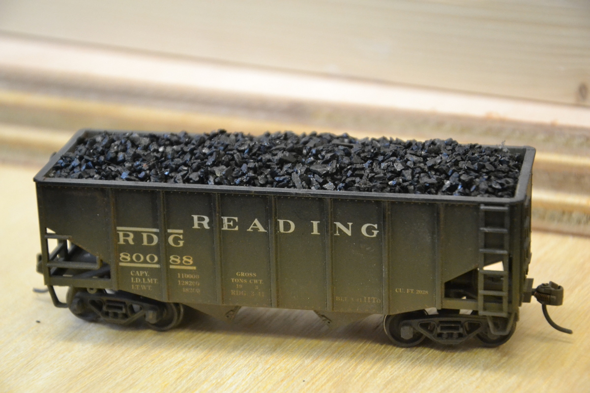
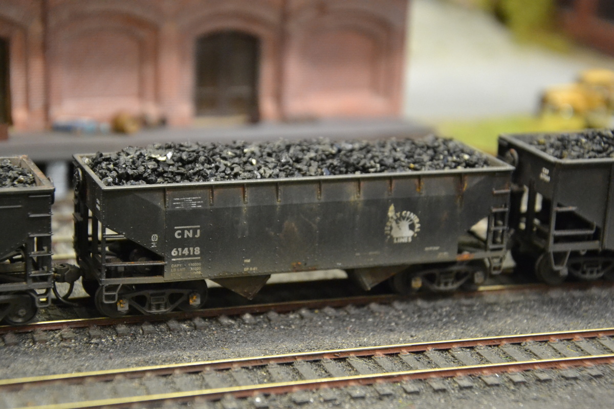
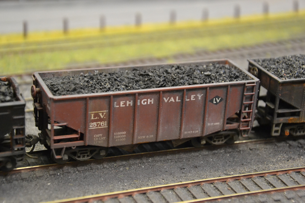
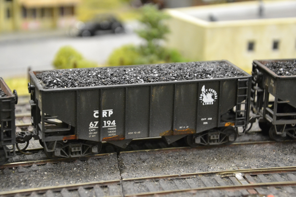
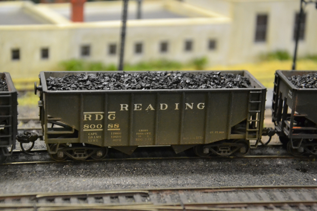
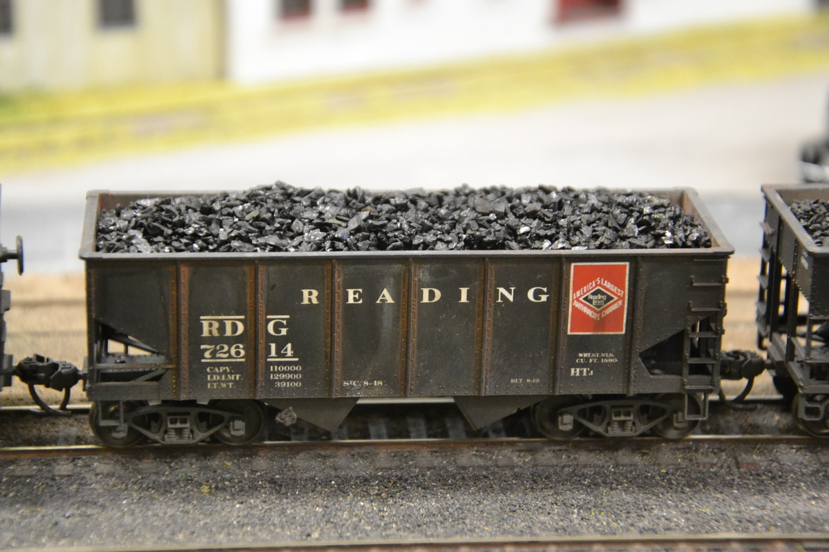
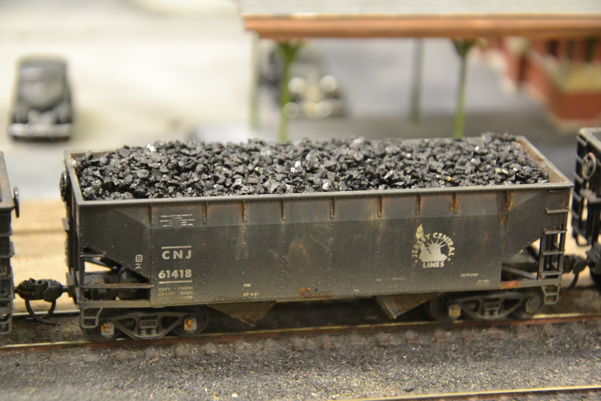
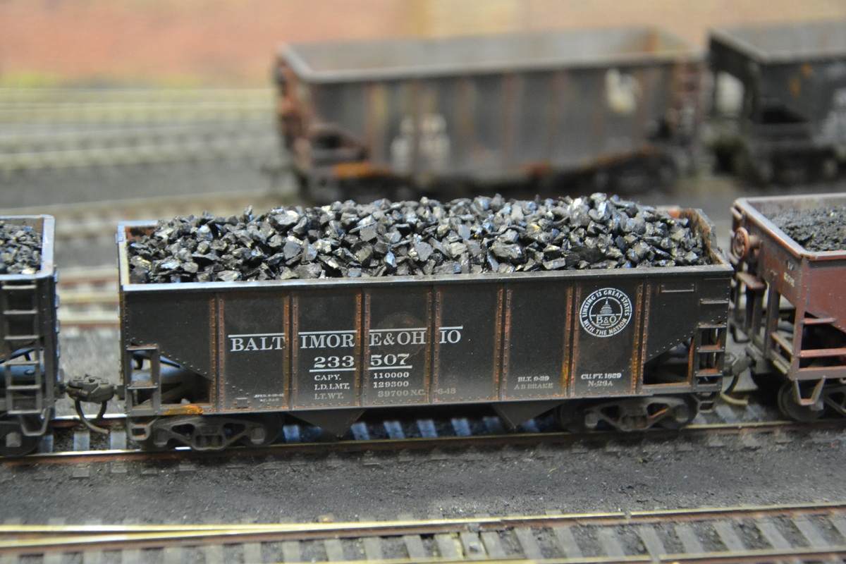
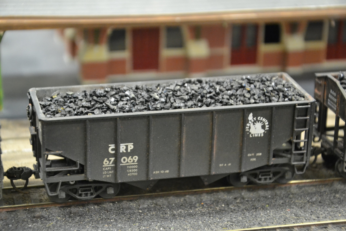
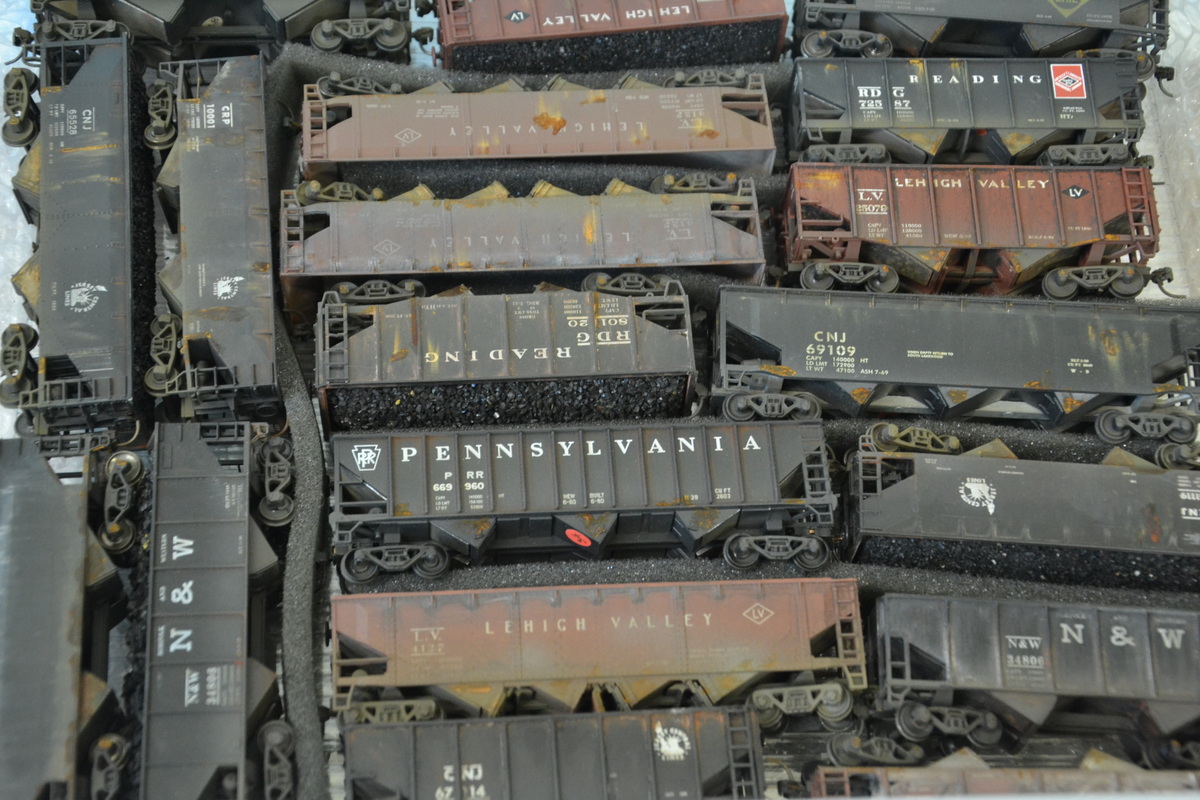
Much of the activity so far in 2013 has been in sorting out rolling stock. Removable coal loads have been prepared for all the hoppers using real coal, sieved down into different size ranges and glued to foam shapers. Photos show the basic process and a variety of the results.
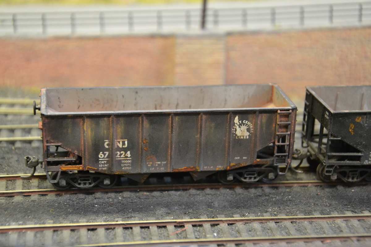
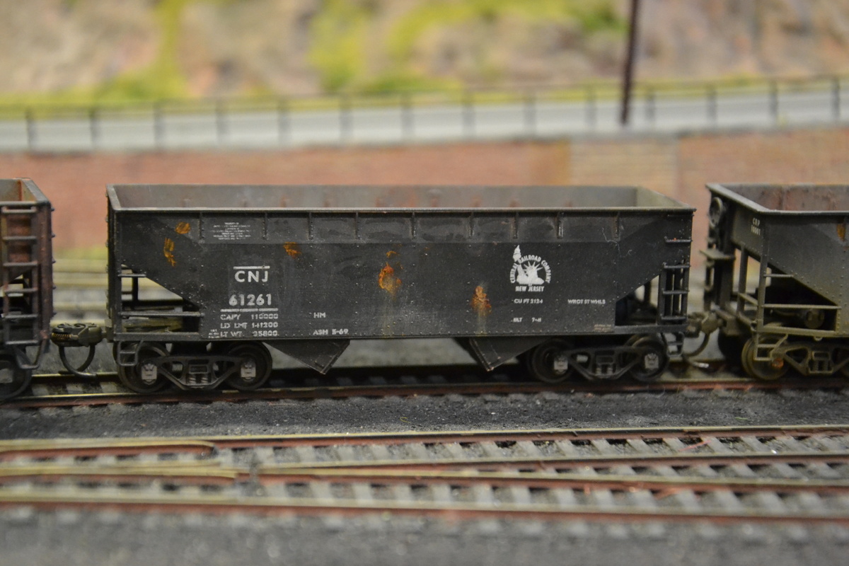
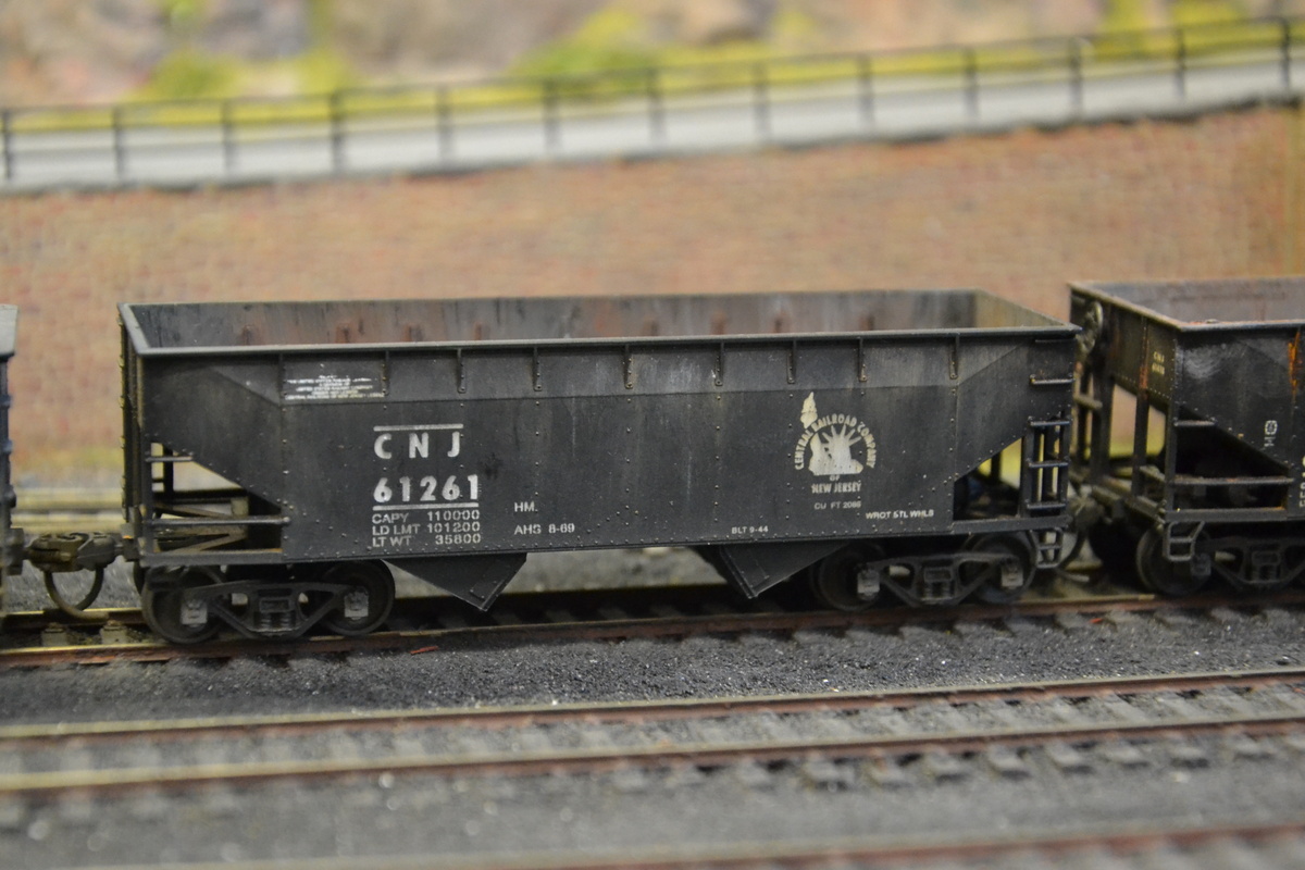
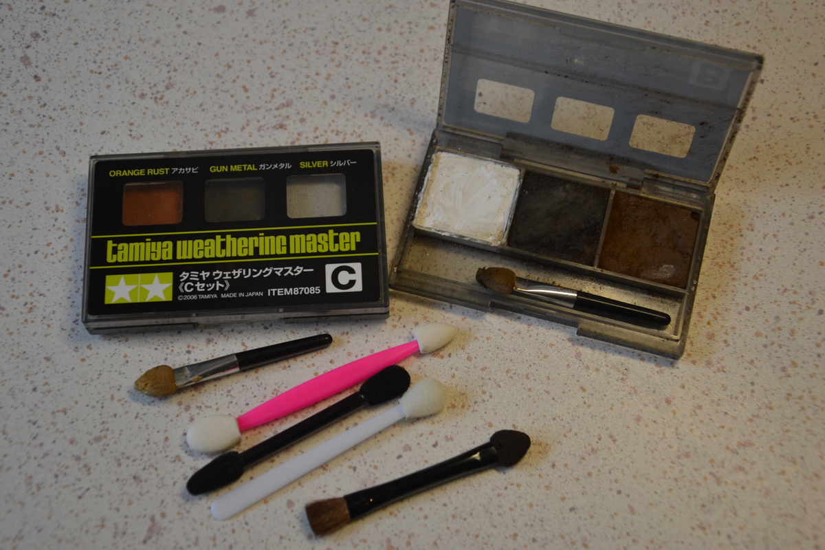
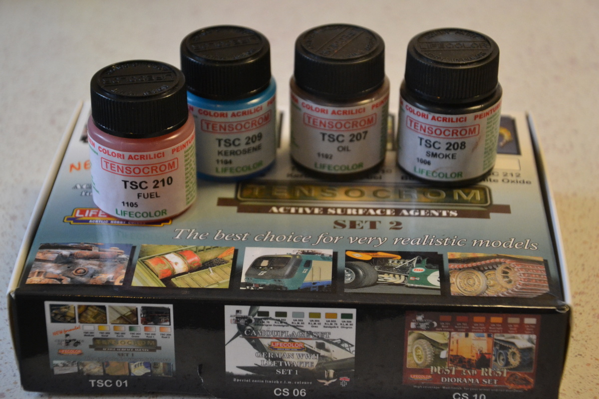
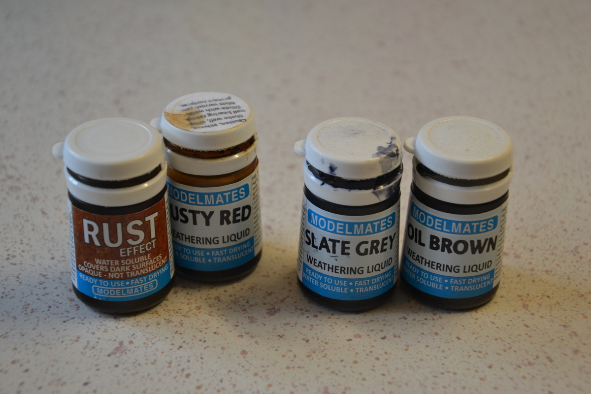
All the hoppers have also been weathered inside and out for consistency using acrylics, weathering powders, Tamiya weathering pads (& make-up applicators – see first photo below), Tensocrom liquids to simulate oil and water spilss, and astonishing Rust effect liquid. ..also an airbrush. The techniques are all described in the UK ‘Model Rail’ DVD by George Dent – ‘The Weathering Expert’ – quite outstanding and worth purchasing even from across the Atlantic, if you can be sure it will work in a US DVD player. These are the main products and implements used .
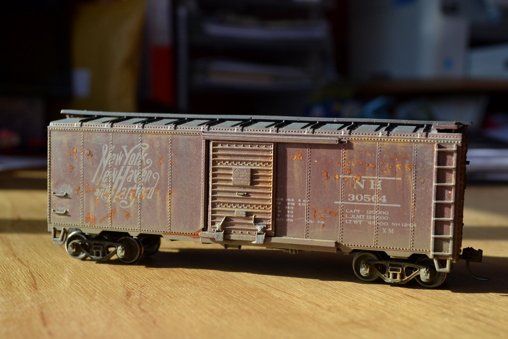
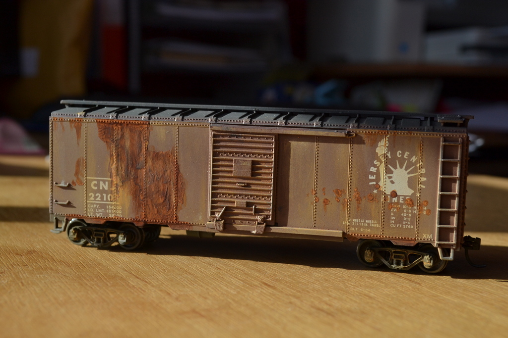
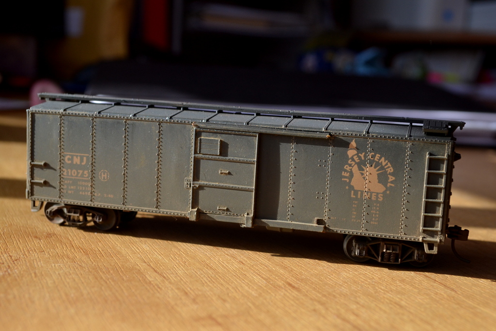
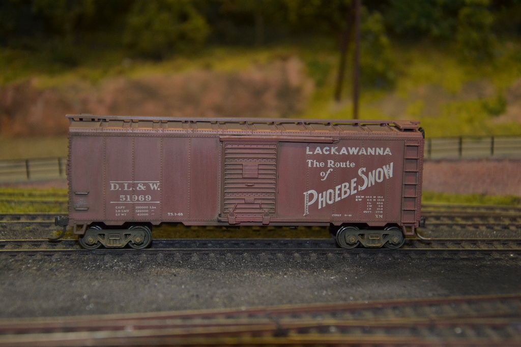
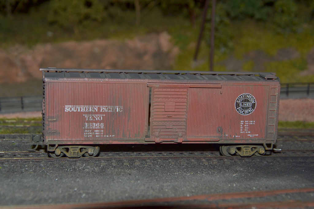
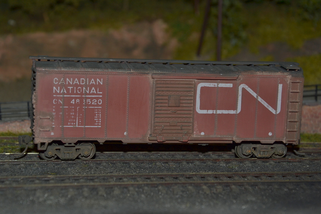
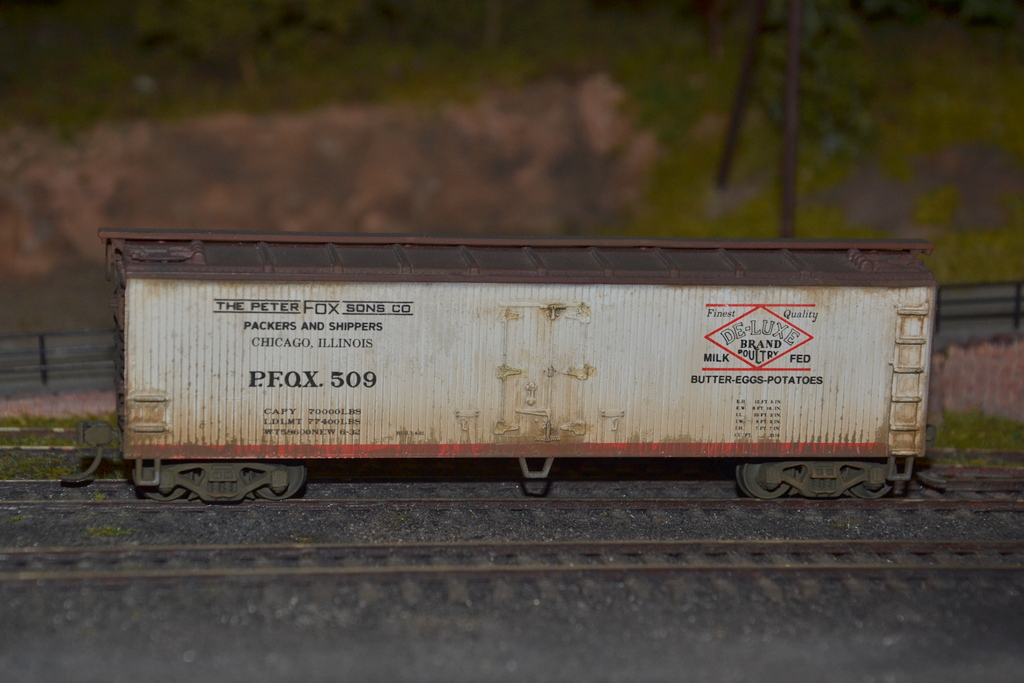
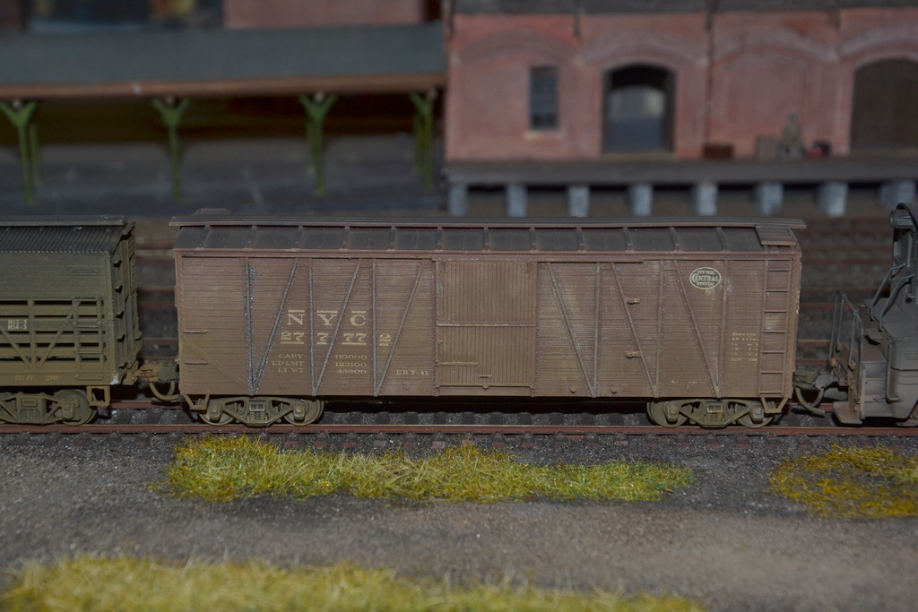
I have also weathered most of the boxcars (some shown below), some tank cars and some switchers. Weathering is hard to photograph, but hopefully some of the photos will give some idea.
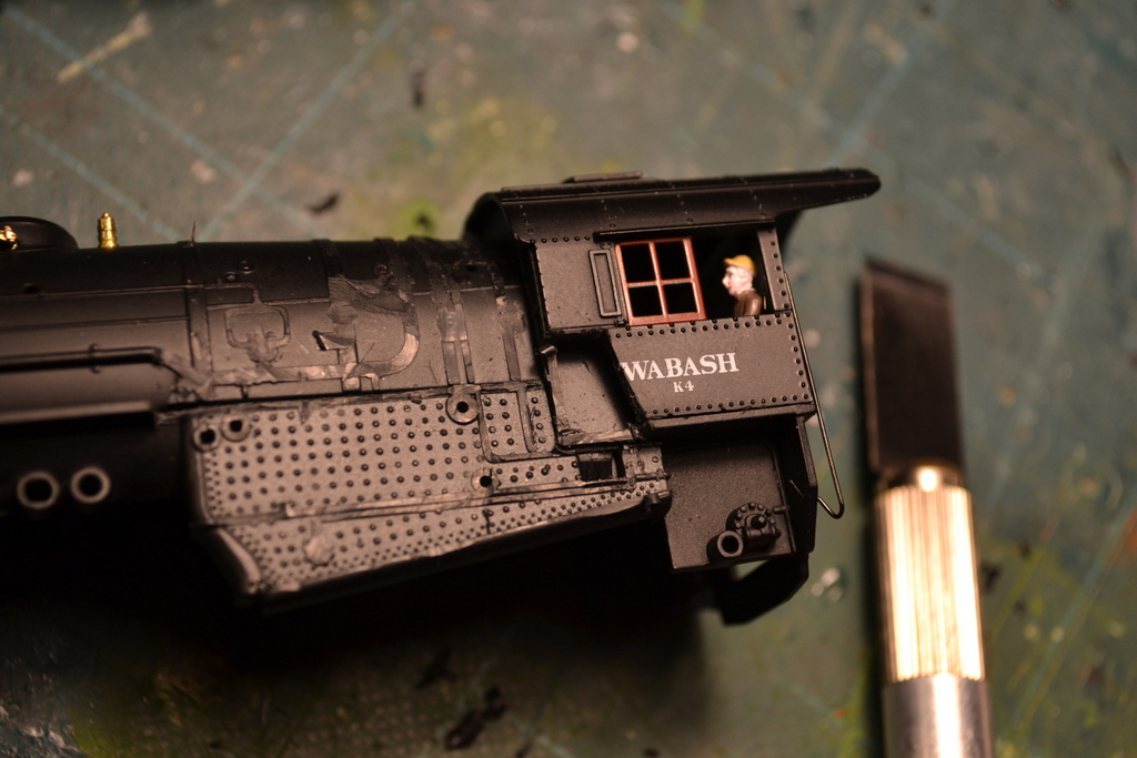
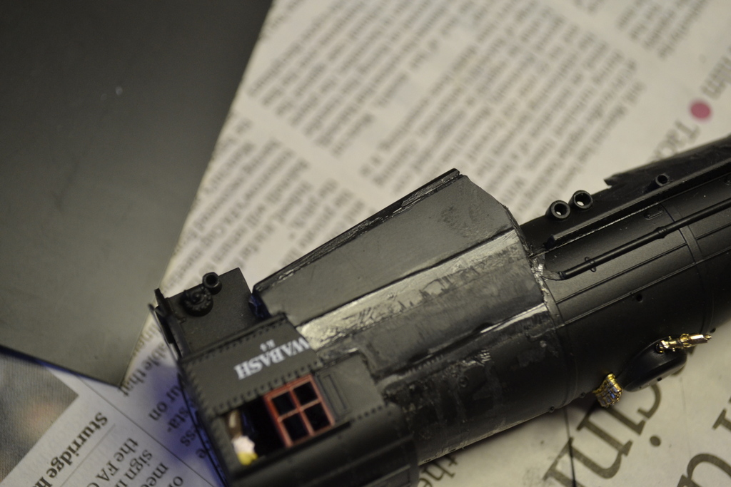
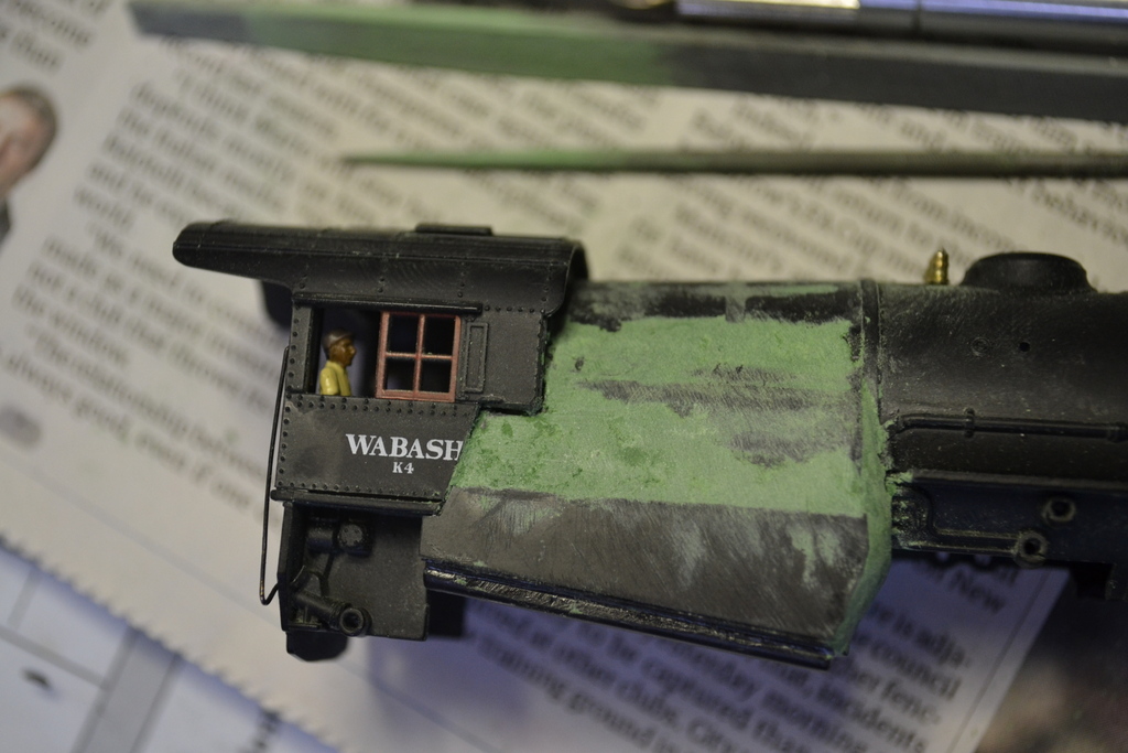
Chris and I have also each started to modify a BLI Mikado to an M3a CNJ Mikado. It is still fairly early days but the photos show the steps in producing the classic Wooton firebox. Many more photos to come but it won’t be quick!